Original cover closer and office equipment having the same

a technology of original cover and office equipment, applied in the direction of wing openers, door/window fittings, construction, etc., can solve the problems of unfavorable impressions of appearance and grease and oil on the hands of the man, so as to prevent lubrication and improve the aesthetics of the original cover

Active Publication Date: 2014-07-24
KEM HONGKONG
View PDF6 Cites 6 Cited by
  • Summary
  • Abstract
  • Description
  • Claims
  • Application Information

AI Technical Summary

Benefits of technology

[0004]The present invention is made to solve the above-mentioned problems, and an object of the invention is to provide an original cover closer which is devised to prevent internal parts from exposure to the outside as much as possible, and to prevent grease and oil, as applied on such internal parts, from smearing ends of an original lying outside the contact glass, when the original is put on the contact glass for the purpose of scanning, as well as smearing hands of a user and / or a worker, when such persons are attaching the original cover closer to the main body and detaching from it.
[0012]As stated above, according to the invention, the cover member can partially cover areas of components of the original cover closer, i.e. the second hinge pin, the actuating member, the first slider, the second slider, as are exposed to the outside, as well as an area of the compression coil spring, as is exposed to the outside. In this manner, the cover member can effectively prevent lubricating or anti-rust grease and oil (those applied onto such areas exposed to the outside) from smearing hands of a user opening and closing the original cover, or a worker attaching the original cover to the main body or detaching the former from the latter at the time of assembling and maintenance, as well as such grease and oil from smearing end of the original lying on the contact glass of the main body.
[0013]Still further, the cover member can prevent the second hinge pin, the actuating member, the first slider, a part of the second slider, and a compression coil spring (which are exposed to the outside, when the original cover is opened) from exposure to the outside, so that it can improve the aesthetics the original cover and assure upgrades to the original cover.

Problems solved by technology

A user can see such internal parts, so their appearance gives unfavorable impressions.
Still further, when the original cover is attached to the main body in assembly, or detached from and attached to it during repair works, a worker often touches the original cover by hands or grasps it, and in this manner, a problem arises in that his hands are smeared with the grease and oil as mentioned above.

Method used


Image

  • Original cover closer and office equipment having the same
  • Original cover closer and office equipment having the same
  • Original cover closer and office equipment having the same

Examples


embodiment 1

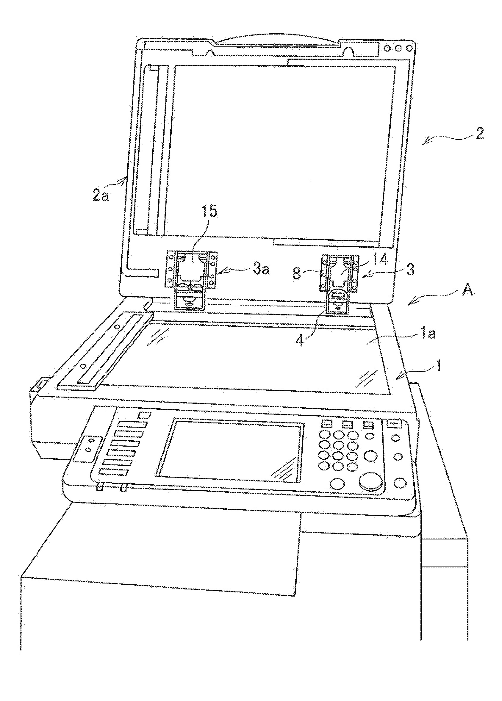
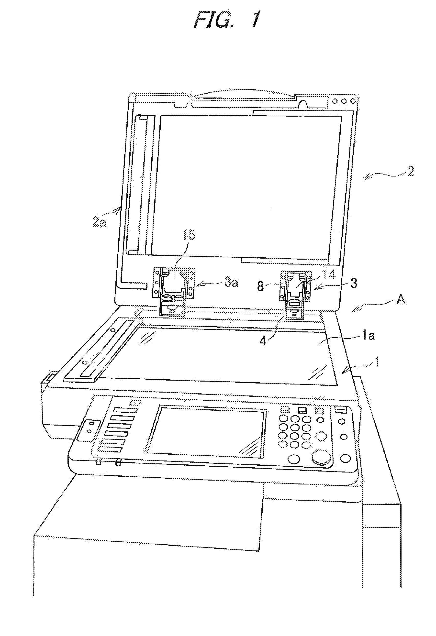
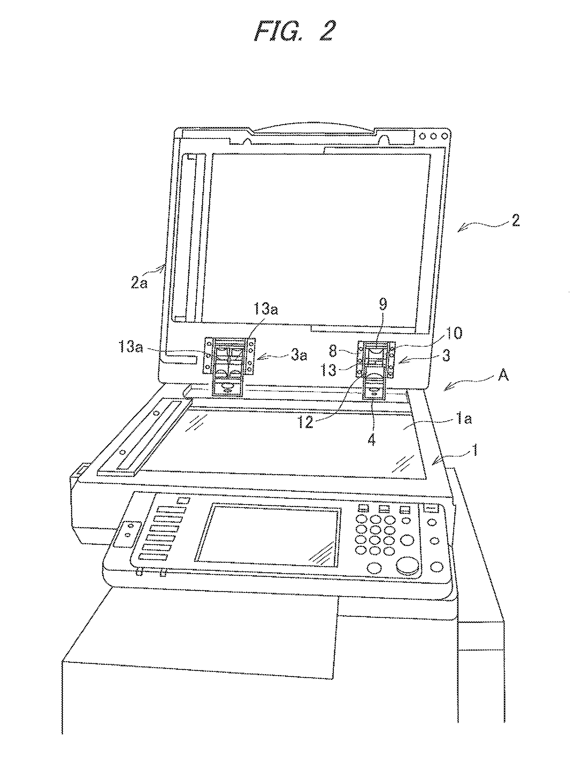
[0035]FIGS. 1 and 2 show a copying machine A which uses an original cover closer 3 according to the present invention. Of the figures, FIG. 1 shows the original cover closer to which cover members 14 and 15 are attached, while FIG. 2 shows the original cover closer without cover members 14 and 15 being attached thereto. If one observes FIG. 2 as above described, one can understand that internal components of the original cover closer 3 (an actuating member 9, a first slider 10, a second slider 12 and compression coil springs 13 or 13a, and others) are exposed to the outside. The same applies to an original cover closer 3a, wherein no reference numerals are given to the corresponding parts.

[0036]According to the drawings, a copying machine A being a sort of office equipment comprises a main body 1, and an original cover 2. An original cover closer 3 according to the present invention is a sort of hinge mechanism for attaching the original cover 2 to the main body 1 of the copying mac...

embodiment 2

[0056]FIGS. 17 and 18 show another embodiment of a cover member. According to the drawings, a cover member 20 according to Embodiment 2 comprises a first cover portion 20a covering a part on the side of an upper portion of a first slider 10, and a second cover portion 20b formed by folding a part of the first cover portion 20a substantially perpendicular to the latter. The cover member 20 is assembled by attaching attaching pieces 20c, 20c provided with attaching holes 20d, 20d and formed by folding a part of the both sides of the first cover portion 20a to a second hinge pin 7. The rest of the components, such as a curved cover portion 20f and cover pieces 20g, 20g, are identical to the corresponding components of Embodiment 1. The cover member 20 is attached to the second hinge pin 7 with edge portions of the attaching pieces 20c, 20c being in contact with a lower surface of a top surface 6a of a supporting member 6, as shown in FIGS. 7, 9, 10, 11 and 13. In this manner, the cover...

embodiment 3

[0059]A cover member according to the present invention is also applicable to an original cover closer of conventional layout, as is described e.g. in JP Laid-Open Patent Application No. 2008-224704: it comprises an attaching member comprising a bottom plate, a leg portion hanging down to a direction perpendicular to the bottom plate and capable of being inserted into an attaching hole provided on a main body, such that the leg portion is detachable from the attaching hole and attachable to the latter, and both side plates erected from both sides of the bottom plate; a supporting member comprising an upper plate, a top plate provided on one end of the upper plate, both side plates provided perpendicular to both sides of the upper plate, wherein the supporting member is assembled by rotatably coupling its both side plates to the both side plates of the attaching member via a hinge pin; a pressure bearing member provided between the both side plates of the attaching member; a slider i...


PUM


Abstract

To provide an original cover closer which prevents inner components from exposure to the outside, when the original cover is opened, and from smears of grease on the end of the original lying on the contact glass, the original cover closer comprises the attaching member, the supporting member assembled by rotatably coupling its own both side plates to the both side plates of the attaching member, the lifting member assembled by rotatably coupling its own both side plates to the both side plates of the supporting member, the pressure bearing member provided between the both side plates of the attaching member, a second slider in contact with the pressure bearing member, and slidably housed between the both side plates of the supporting member; an actuating member attached to the side on which the both side plates of the attaching member rotate via said second hinge pin; a first slider in contact with the actuating member, held by the holding pieces and slidably housed between the both side plates of said supporting member, and a compression coil spring resiliently provided between the first slider and the second slider, wherein a cover member is fixed to the supporting member, for covering at least in part areas of components such as the actuating member, the first slider and the second slider which are exposed to the outside.

Description

FIELD OF THE INVENTION[0001]The present invention relates to an original cover closer suitable in use for office equipment including a copying machine, a printer, a facsimile, a scanner, and the like; it further relates to office equipment provided with the mentioned automatic original cover closer.BACKGROUND ART[0002]An original cover is attached via original cover closers to a main body of office equipment such as a copying machine, a printer, a facsimile, a scanner. Each original cover closer is a kind of hinge mechanism, of which the layout is as disclosed in JP Laid-Open Patent Application H11-95339: it comprises an attaching member comprising a bottom plate attached to the main body of office equipment; both side plates erected from both sides of the bottom plate; a supporting member comprising an upper plate and both side plates provided to hang down perpendicular to both sides of the upper plate, wherein the supporting member is assembled by rotatably coupling its both side ...

Claims


Application Information

Patent Timeline
Patent Type & Authority Applications(United States)
IPC IPC(8): E05F1/10
CPCE05F1/105E05Y2900/608E05D3/12E05Y2201/638E05Y2800/73E05F1/1261
Inventor YABUKOSHI, KENTAROKONDO, TETSUO
Owner KEM HONGKONG
Why Eureka
Try Eureka