

Sorting screen for sorting material and rotor body for such a sorting screen
a sorting screen and material technology, applied in the direction of screening, solid separation, chemistry apparatus and processes, etc., can solve the problem of a relatively high investment in the replacement of all the screen discs of the screening bed, and achieve the effect of low cos
- Summary
- Abstract
- Description
- Claims
- Application Information
AI Technical Summary
Benefits of technology
Problems solved by technology
Method used
Image

Examples
Embodiment Construction
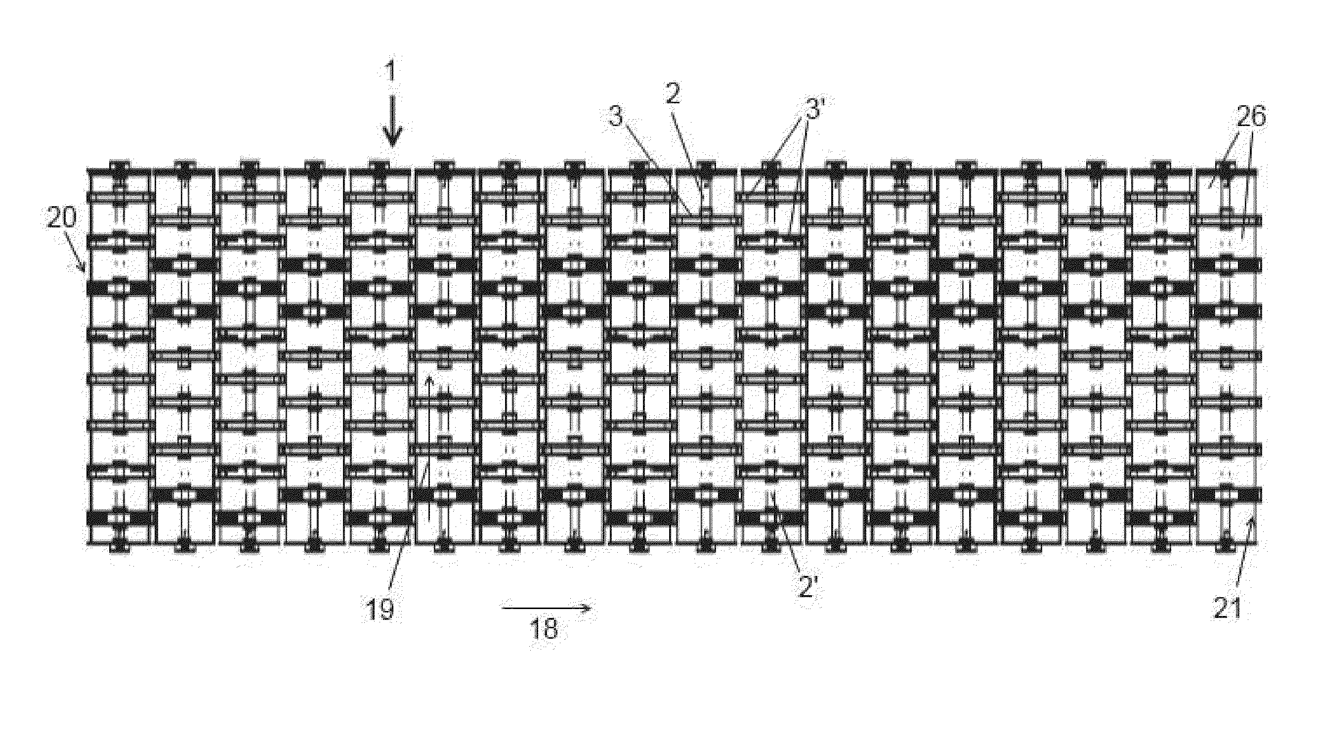
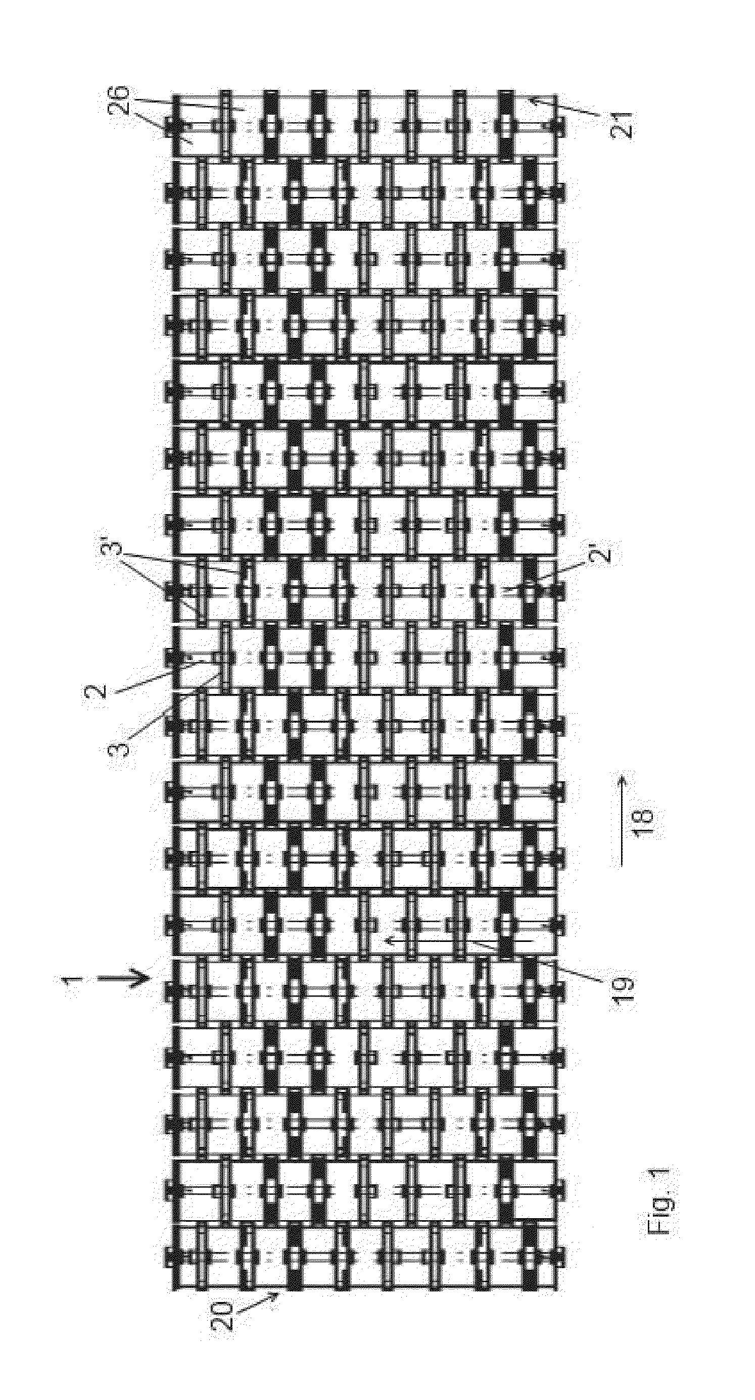
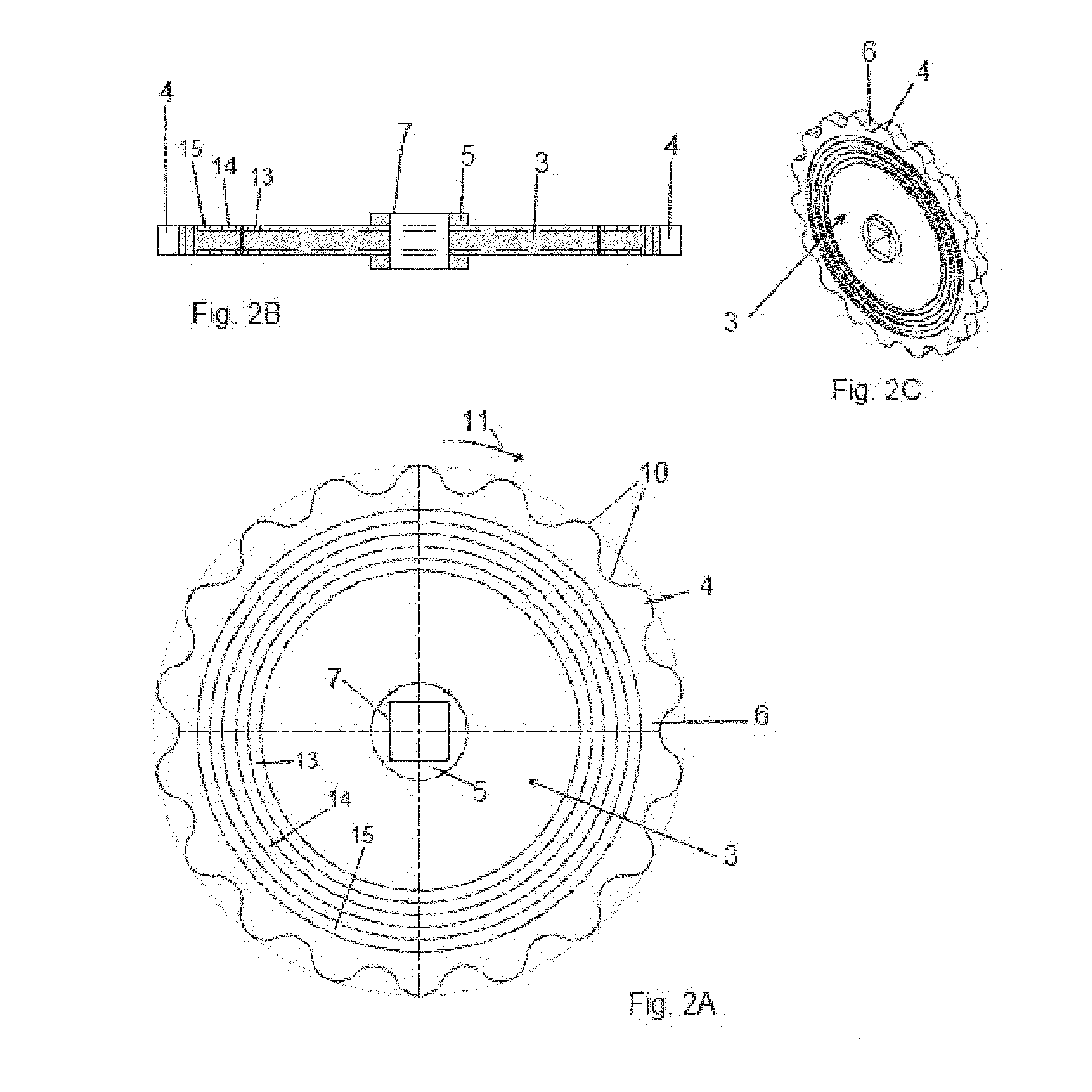
[0013]First, an example of a sorting screen 1 as shown in FIG. 1 is described. The sorting screen 1 is equipped with a row of rotatable shafts 2 mutually spaced in a conveying direction 18 and drivable in a common sense of rotation. Each shaft 2 extends transversally to the conveying direction 18. For driving rotation of the shafts 2, the shafts are coupled in a manner known per se to a motor via a drive train. Each of the shafts 2 carries a row of radially projecting rotor bodies 3 for intermittently urging material on the sorting screen conveyor upward and in conveying direction 18 when the shafts 2 are driven for rotation in a sense in which the upper parts of the rotor bodies 3 move with a directional component in the conveying direction 18. The rotor bodies 3 of each of the rows are mutually spaced in longitudinal direction 19 of the respective shaft 2. In operation, the circumference of each rotor body 3 moves rotationally along a rotary trajectory and the rotary trajectories ...
PUM
 Abstract
Description
Claims
Application Information