Module board

Active Publication Date: 2014-07-24
MURATA MFG CO LTD
View PDF4 Cites 9 Cited by
  • Summary
  • Abstract
  • Description
  • Claims
  • Application Information

AI Technical Summary

Benefits of technology

[0006]Accordingly, it is a primary object of the present invention to provide a module board that can suppress the interference

Problems solved by technology

However, the shield layer interferes with the component disposed on the s

Method used


Image

  • Module board
  • Module board
  • Module board

Examples


embodiment

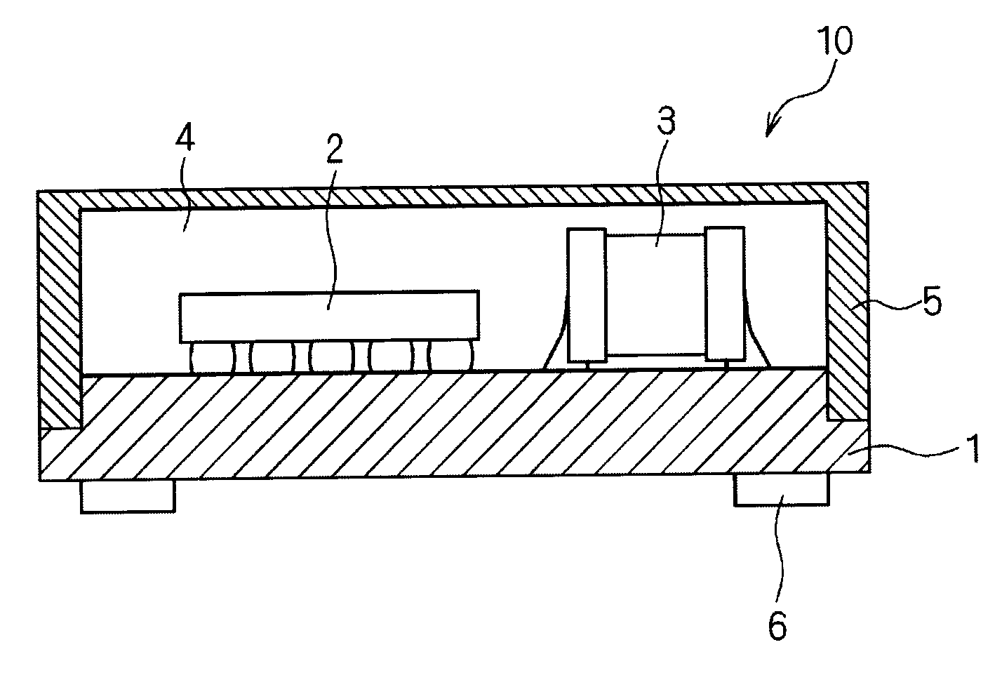
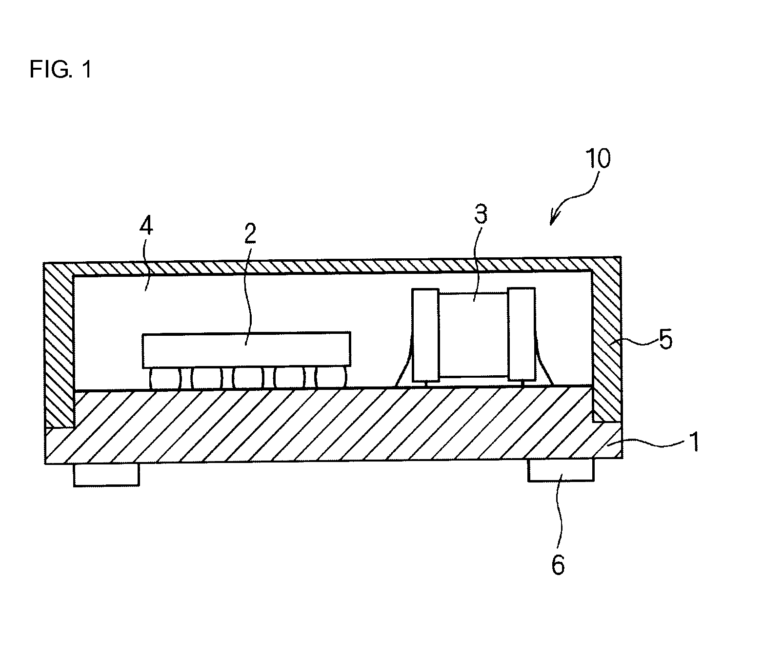
[0025]FIG. 1 is a schematic view showing a structure of a module board 10 according to an embodiment of the present invention. As shown in FIG. 1, the module board 10 includes a base substrate 1, a plurality of electronic components 2 and 3 mounted on one of the principal surfaces (the first principal surface) of the base substrate 1, a sealing resin 4 formed so as to seal the plurality of the mounted electronic components 2 and 3, a shield layer 5 covering a top surface and side surfaces of the sealing resin 4 with a conductive material, and a terminal electrode 6 formed on the other principal surface (the second principal surface) of the base substrate 1. The second principal surface is disposed opposite to the first principal surface on which the electronic components 2 and 3 are mounted.

[0026]From the viewpoint of the material, the base substrate 1 includes, but is not limited to, an organic substrate or a ceramic substrate such as a low temperature co-fired ceramic (LTCC) subst...


PUM


Abstract

A module board includes a base substrate. Electronic components are mounted on a first principal surface of the base substrate. The mounted electronic components are sealed by a sealing resin containing an SiO2 filler. A top surface and side surfaces of the sealing resin are covered with a shield layer containing a carbon filler, which is flat powder, as a conductive component. A terminal electrode is formed on a second principal surface of the base substrate that is disposed opposite to the first principal surface of the base substrate.

Description

BACKGROUND OF THE INVENTION[0001]1. Field of the Invention[0002]The present invention relates to a module board. More particularly, the present invention relates to, for example, a module board of a circuit module or the like in which a sealing resin is covered with a shield layer. The sealing resin is formed so as to seal an electronic component mounted on one of the principal surfaces of a base substrate.[0003]2. Description of the Related Art[0004]An example of a circuit module of a related art, serving as a background of the invention, is disclosed in, for example, Japanese Unexamined Patent Application Publication No. 2004-172176 (Patent Document 1). The circuit module disclosed in Patent Document 1 is one in which a component that is disposed on a substrate is covered with an insulating layer. This circuit module includes a shield layer connected to a ground electrode provided on the substrate. In the circuit module, the shield layer is formed of a conductive resin and, in gen...

Claims


Application Information

Patent Timeline
IPC IPC(8): H05K1/02
CPCH05K1/0216H05K1/0218H05K3/284H05K2201/0245H05K2201/0323H05K2201/0715H05K2203/1316H01L24/97H01L2224/16225H01L2924/19105H01L2924/15787H01L2924/00
Inventor KATAOKA, YUJIKANRYO, KOICHI
Owner MURATA MFG CO LTD
Why Eureka
Try Eureka