Battery case

a battery case and battery technology, applied in the field of battery cases, can solve the problems of increasing cost, bulky battery cases, and worsening productivity, and achieve the effect of lowering cost and improving productivity

Inactive Publication Date: 2014-07-24
TOYOTA IND CORP
View PDF4 Cites 17 Cited by
  • Summary
  • Abstract
  • Description
  • Claims
  • Application Information

AI Technical Summary

Benefits of technology

[0013]One aspect of the present invention can secure a space for mounting a battery case under a floor of a vehicle while lowering cost and improving productivity.

Problems solved by technology

However, the following problem exists in the prior art mentioned above.
This increases cost and worsens productivity.
That also makes the battery case bulky, whereby a space for mounting the battery case may be hard to secure.

Method used


Image

  • Battery case
  • Battery case
  • Battery case

Examples


Embodiment Construction

[0019]In the following, an embodiment of the battery case in accordance with one aspect of the present invention will be explained in detail with reference to the drawings.

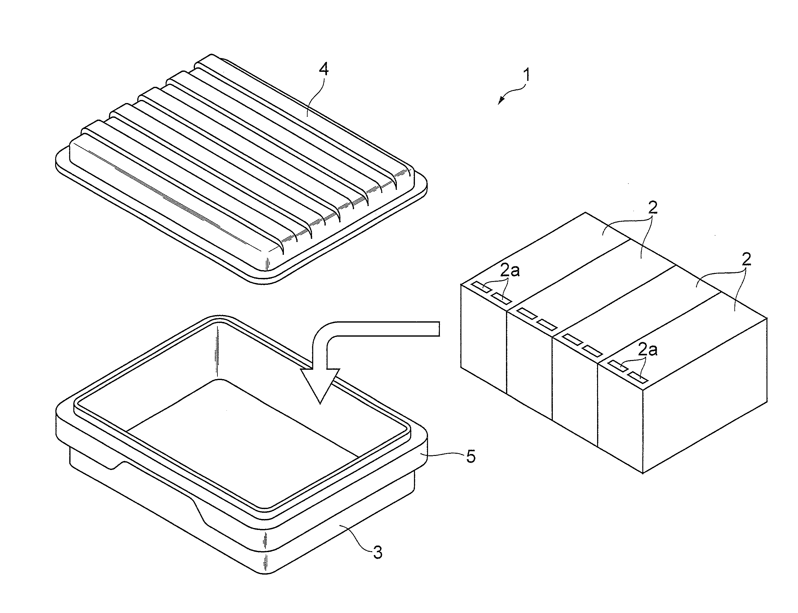
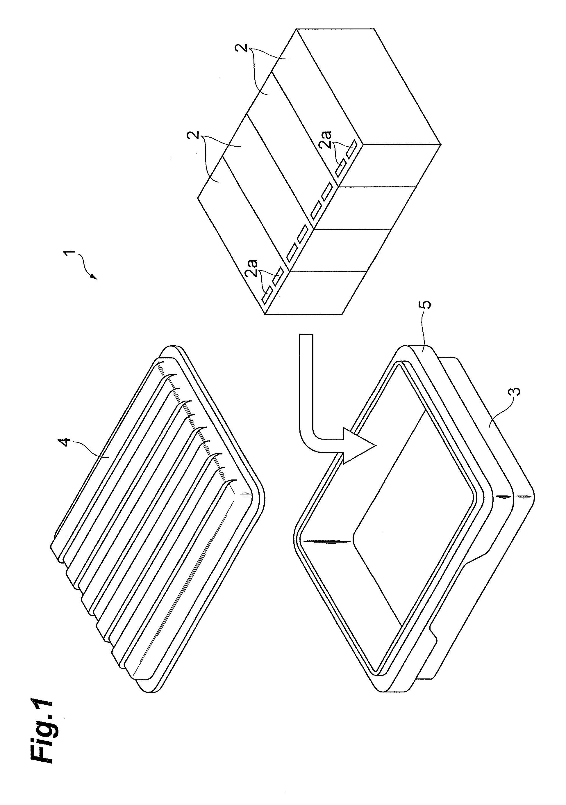
[0020]FIG. 1 is an exploded (partly abridged) perspective view illustrating an embodiment of the battery case in accordance with one aspect of the present invention. In the drawing, the battery case 1 of this embodiment is mounted under a floor of a vehicle such as an electric vehicle.

[0021]The battery case 1 comprises a box-shaped case body 3 containing a plurality of (4 here) battery modules 2 in a row and a cover 4 for closing over an opening of the case body 3. Each battery module 2 is constructed by connecting a plurality of battery cells (e.g., lithium-ion cells), which are not depicted, together. The upper face of each battery module 2 is provided with two exhaust ports 2a for letting out high-temperature gases generated from the batteries because of failures such as short-circuiting.

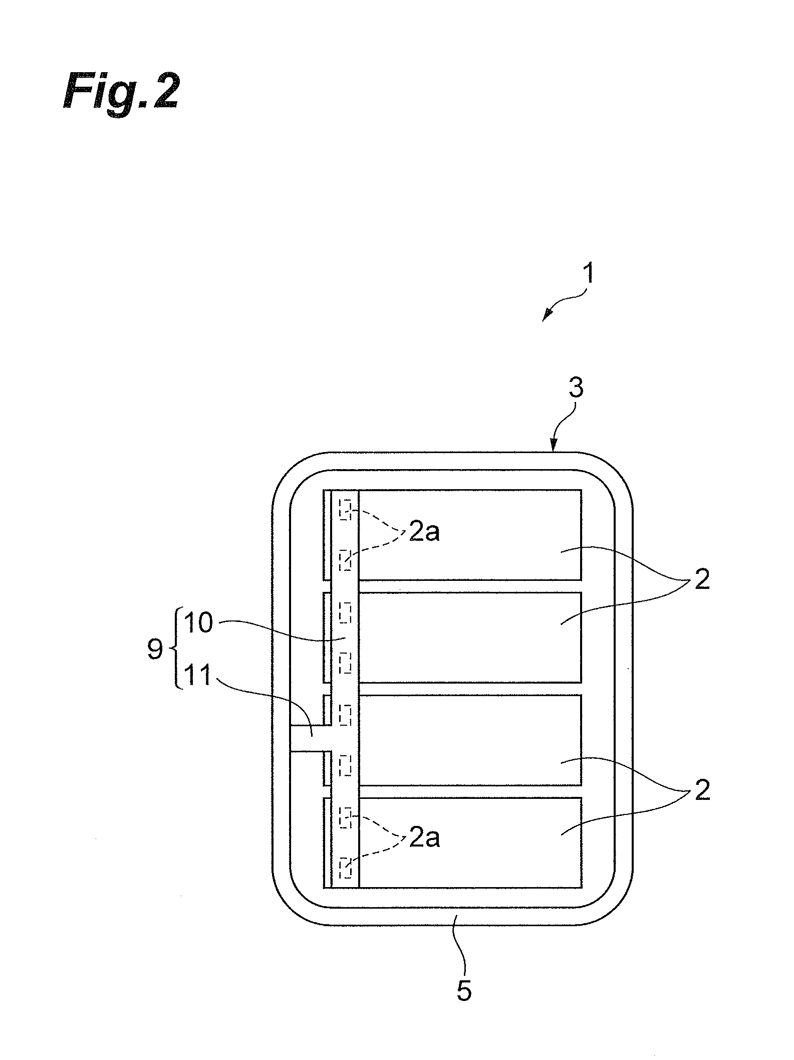
[0022]As FIGS. 2 and 3 ...


PUM

PropertyMeasurementUnit
temperatureaaaaaaaaaa
timeaaaaaaaaaa
structuresaaaaaaaaaa

Abstract

A battery case for mounting under a floor of a vehicle comprises a case body containing a battery module and a cover for closing over an opening of the case body. A reinforcement member for reinforcing the case body is attached to an outer surface of the case body. The case body is provided with a gas circulation hole for letting a gas flow from within the case body into the reinforcement member. The reinforcement member is provided with a gas exhaust port for letting out the gas having flown into the reinforcement member.

Description

BACKGROUND OF THE INVENTION[0001]1 . Field of the Invention[0002]One aspect of the present invention relates to a battery case for mounting under a floor of a vehicle.[0003]2. Related Background Art[0004]As a conventional battery case, one disclosed in Japanese Patent Application Laid-Open No. 2011-70872 (hereinafter referred to as “Patent Literature 1”) has been known, for example. The battery case disclosed in Patent Literature 1 comprises a housing for containing a battery block, a substrate provided so as to cover an open end of the housing, a partition member disposed above the substrate, and a lid provided so as to cover the upper side of the partition member. The partition member is provided with exhaust passages for letting out high-temperature gases generated from batteries of the battery block by short-circuiting and the like and an exhaust hole communicating with the exhaust passages.SUMMARY OF THE INVENTION[0005]However, the following problem exists in the prior art ment...

Claims


Application Information

Patent Timeline
Patent Type & Authority Applications(United States)
IPC IPC(8): H01M2/10H01M10/6556H01M50/204H01M50/271H01M50/358H01M50/367
CPCH01M10/5057H01M2/1083B60L50/64H01M50/271H01M50/358H01M50/367H01M50/204H01M10/625H01M10/6563H01M10/6556H01M10/613Y02T10/70Y02E60/10H01M50/308
Inventor OHGITANI, IKKEIOJIMA, YOSHIOFUKAGAWA, TAKAHIRO
Owner TOYOTA IND CORP
Why Eureka
Try Eureka