Audio signal restoration device and audio signal restoration method

a restoration device and audio signal technology, applied in the field of audio signal restoration device and audio signal restoration method, can solve the problems of poor sound quality of the conventional telephone circuit and poor sound quality, and achieve the effect of preventing the corruption of the harmonic structure of the audio signal and more intelligible audio restoration signal

Inactive Publication Date: 2014-07-24
MITSUBISHI ELECTRIC CORP
View PDF5 Cites 8 Cited by
  • Summary
  • Abstract
  • Description
  • Claims
  • Application Information

AI Technical Summary

Benefits of technology

[0013]According to the present invention, since it generates the sound source signal from the audio signal in the first frequency band which does not undergo the noise suppression processing, it can prevent the corruption of the harmonic structure of the audio signal. Accordingly, even when the noise is mixed at a low S / N, it can generate the sound source signal using information about the harmonic structure the audio signal originally has. As a result, it can generate a more intelligible audio restoration signal.

Problems solved by technology

Accordingly, the quality of sound of the conventional telephone circuit is not so good.
In addition, in digital speech communication such as a mobile phone, since the bandwidth is limited as in the analog circuit because of the bit rate limiting, the quality of sound is not so good as well.

Method used


Image

  • Audio signal restoration device and audio signal restoration method
  • Audio signal restoration device and audio signal restoration method
  • Audio signal restoration device and audio signal restoration method

Examples


embodiment 1

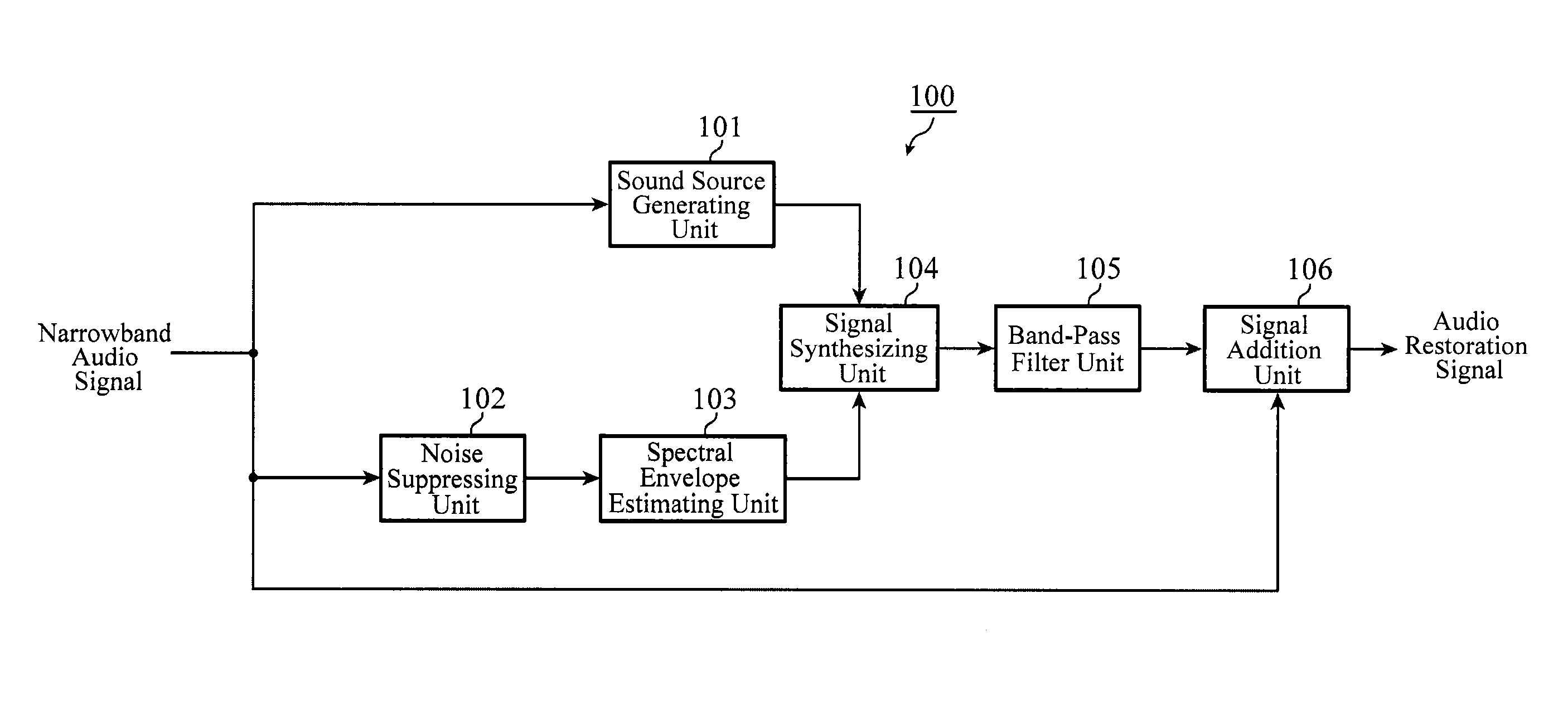
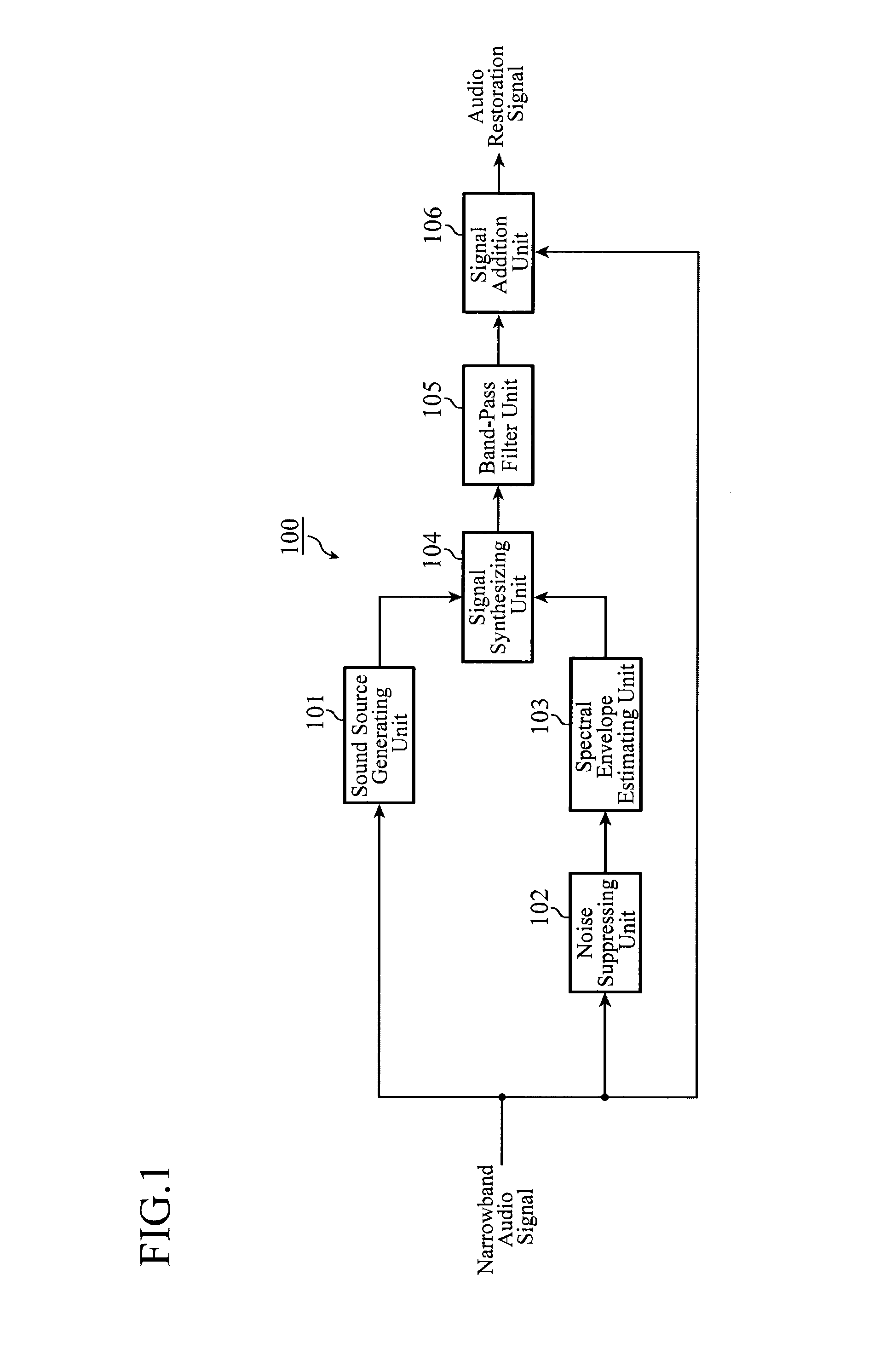
[0022]FIG. 1 is a block diagram showing a configuration of the audio signal restoration device 100 of the present embodiment 1.

[0023]The audio signal restoration device 100 is a device that uses as its input an audio signal of a narrow band (referred to as the narrowband audio signal from now on) which passes through the band limiting of the audio signal of a broad band (referred to as the broadband audio signal from now on), and generates a broadband audio restoration signal by generating a signal of a limited band (referred to as the expansion band from now on) and by combining it with the narrowband audio signal.

[0024]In FIG. 1, a sound source generating unit 101 receives a narrowband audio signal as its input, generates a sound source signal including the fine structure of the expansion band, and supplies it to the signal synthesizing unit 104. A noise suppressing unit 102 receives the narrowband audio signal as its input, executes noise suppression, and supplies the noise suppr...

embodiment 2

[0055]FIG. 3 is a block diagram showing a configuration of an audio signal restoration device 100 of the present embodiment 2. In FIG. 3, the same or like components to those of FIG. 1 are designated by the same reference numerals, and their description will be omitted.

[0056]The audio signal restoration device 100 of the present embodiment 2 is a variation of the embodiment 1, which has a weak noise suppressing unit 107 introduced as preprocessing of the sound source generating unit 101.

[0057]As described before, the conventional audio signal restoration technique has a problem in that when noise is mixed into the input narrowband audio signal at a low S / N, the noise estimation does not work well, and the amount of noise is estimated excessively. In that case, since it executes noise suppression in accordance with the excessively estimated amount of noise, it suppresses not only the noise components of the narrowband audio signal but also the audio component, thereby sometimes corru...

embodiment 3

[0062]FIG. 4 is a block diagram showing a configuration of an audio signal restoration device 100 of the present embodiment 3. In FIG. 4, the same or like components to those of FIG. 1 are designated by the same reference numerals, and their description will be omitted.

[0063]The audio signal restoration device 100 of the present embodiment 3, which is a variation of the embodiment 1, changes the input to the signal addition unit 106a from the narrowband audio signal to the narrowband audio signal noise suppressed by the noise suppressing unit 102.

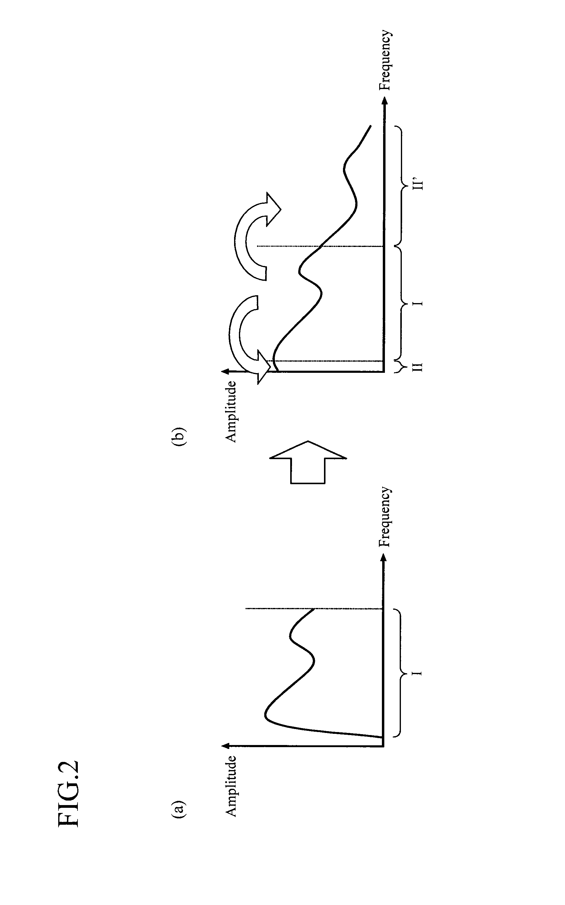
[0064]The signal addition unit 106a received as its input the narrowband audio signal noise suppressed by the noise suppressing unit 102 (for example, the band I shown in FIG. 2) and the pseudo-audio signal band limited by the band-pass filter unit 105 (for example, bands II and II′ shown in FIG. 2), and adds the two signals to generate the broadband audio restoration signal.

[0065]As described above, according to the embodiment 3, the signa...


PUM


Abstract

A sound source generating unit 101 generates from a narrowband audio signal not passing through noise suppression a sound source signal including a fine structure of a band to be restored. On the other hand, a noise suppressing unit 102 performs noise suppression of the narrowband audio signal and a spectral envelope estimating unit 103 estimates an spectral envelope of the band to be restored. A signal synthesizing unit 104 generates a pseudo-audio signal by combining the sound source signal and the spectral envelope, and the band-pass filter unit 105 passes the pseudo-audio signal of the band to be restored, and the signal addition unit 106 generates a broadband audio restoration signal by adding the pseudo-audio signal of the band to be restored to the narrowband audio signal.

Description

TECHNICAL FIELD[0001]The present invention relates to an audio signal restoration device and audio signal restoration method that expand an audio signal, the frequency band of which is limited to a narrowband because of passing through a transmission line such as a telephone circuit, to a broadband audio signal, and that restore an audio signal in a band deteriorated or impaired because of noise suppression, audio compression and the like.BACKGROUND ART[0002]In an analog telephone system, the frequency band of speech transmitted through a telephone circuit is band limited to a narrow band such as 300-3400 Hz. Accordingly, the quality of sound of the conventional telephone circuit is not so good. In addition, in digital speech communication such as a mobile phone, since the bandwidth is limited as in the analog circuit because of the bit rate limiting, the quality of sound is not so good as well.[0003]With respect to the problem, an audio signal restoration technique is known which g...

Claims


Application Information

Patent Timeline
Patent Type & Authority Applications(United States)
IPC IPC(8): G10L19/012
CPCG10L19/012G10L21/0388G10L21/0208
Inventor HOSOYA, KOSUKEFURUTA, SATORUYAMAURA, TADASHI
Owner MITSUBISHI ELECTRIC CORP
Why Eureka
Try Eureka