Audio signal restoration device and audio signal restoration method
a restoration device and audio signal technology, applied in the field of audio signal restoration device and audio signal restoration method, can solve the problems of poor sound quality of the conventional telephone circuit and poor sound quality, and achieve the effect of preventing the corruption of the harmonic structure of the audio signal and more intelligible audio restoration signal
- Summary
- Abstract
- Description
- Claims
- Application Information
AI Technical Summary
Benefits of technology
Problems solved by technology
Method used
Image
Examples
embodiment 1
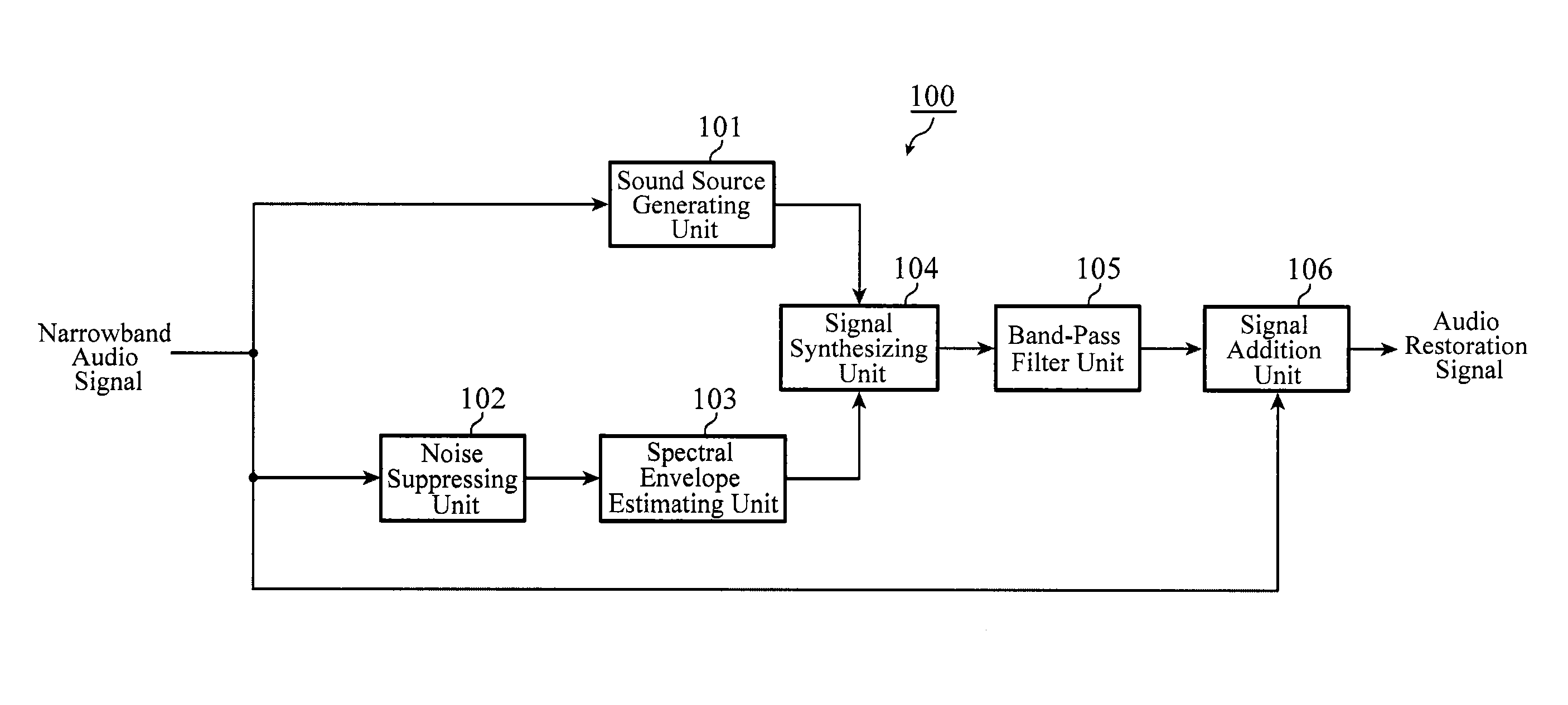
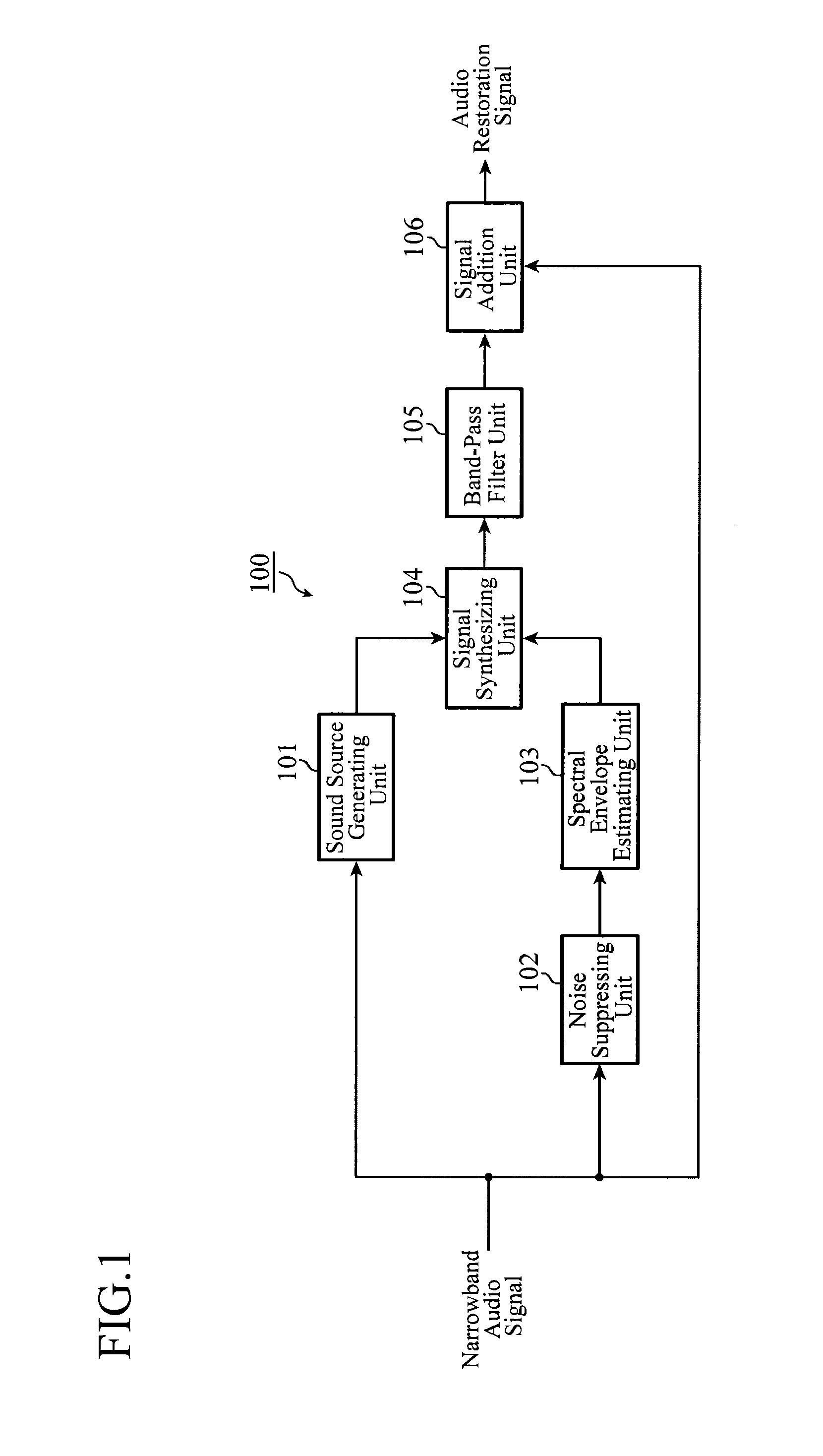
[0022]FIG. 1 is a block diagram showing a configuration of the audio signal restoration device 100 of the present embodiment 1.
[0023]The audio signal restoration device 100 is a device that uses as its input an audio signal of a narrow band (referred to as the narrowband audio signal from now on) which passes through the band limiting of the audio signal of a broad band (referred to as the broadband audio signal from now on), and generates a broadband audio restoration signal by generating a signal of a limited band (referred to as the expansion band from now on) and by combining it with the narrowband audio signal.
[0024]In FIG. 1, a sound source generating unit 101 receives a narrowband audio signal as its input, generates a sound source signal including the fine structure of the expansion band, and supplies it to the signal synthesizing unit 104. A noise suppressing unit 102 receives the narrowband audio signal as its input, executes noise suppression, and supplies the noise suppr...
embodiment 2
[0055]FIG. 3 is a block diagram showing a configuration of an audio signal restoration device 100 of the present embodiment 2. In FIG. 3, the same or like components to those of FIG. 1 are designated by the same reference numerals, and their description will be omitted.
[0056]The audio signal restoration device 100 of the present embodiment 2 is a variation of the embodiment 1, which has a weak noise suppressing unit 107 introduced as preprocessing of the sound source generating unit 101.
[0057]As described before, the conventional audio signal restoration technique has a problem in that when noise is mixed into the input narrowband audio signal at a low S / N, the noise estimation does not work well, and the amount of noise is estimated excessively. In that case, since it executes noise suppression in accordance with the excessively estimated amount of noise, it suppresses not only the noise components of the narrowband audio signal but also the audio component, thereby sometimes corru...
embodiment 3
[0062]FIG. 4 is a block diagram showing a configuration of an audio signal restoration device 100 of the present embodiment 3. In FIG. 4, the same or like components to those of FIG. 1 are designated by the same reference numerals, and their description will be omitted.
[0063]The audio signal restoration device 100 of the present embodiment 3, which is a variation of the embodiment 1, changes the input to the signal addition unit 106a from the narrowband audio signal to the narrowband audio signal noise suppressed by the noise suppressing unit 102.
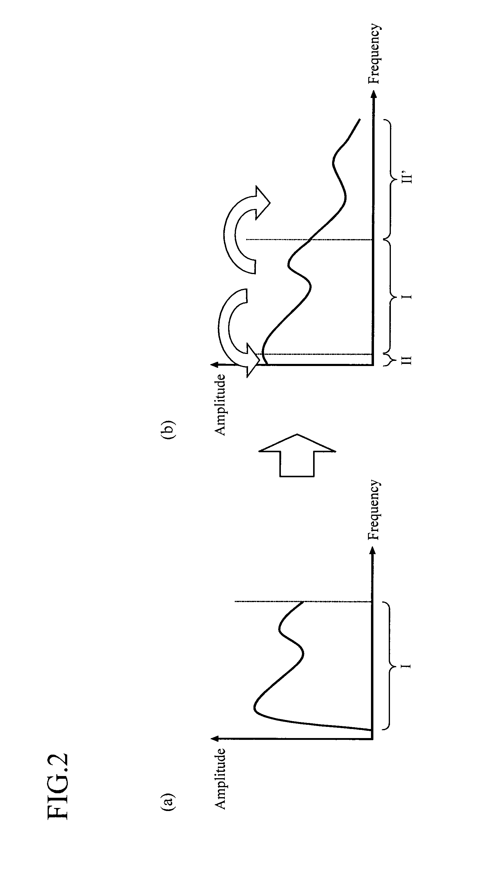
[0064]The signal addition unit 106a received as its input the narrowband audio signal noise suppressed by the noise suppressing unit 102 (for example, the band I shown in FIG. 2) and the pseudo-audio signal band limited by the band-pass filter unit 105 (for example, bands II and II′ shown in FIG. 2), and adds the two signals to generate the broadband audio restoration signal.
[0065]As described above, according to the embodiment 3, the signa...
PUM
 Abstract
Description
Claims
Application Information
 - R&D
- Intellectual Property
- Life Sciences
- Materials
- Tech Scout
- Unparalleled Data Quality
- Higher Quality Content
- 60% Fewer Hallucinations
Browse by: Latest US Patents, China's latest patents, Technical Efficacy Thesaurus, Application Domain, Technology Topic, Popular Technical Reports.
© 2025 PatSnap. All rights reserved.Legal|Privacy policy|Modern Slavery Act Transparency Statement|Sitemap|About US| Contact US: help@patsnap.com


