
Closure Arrangement for Cans

Inactive Publication Date: 2014-07-31
BRASILATA S A EMBALAGENS METALICAS
View PDF14 Cites 0 Cited by
  • Summary
  • Abstract
  • Description
  • Claims
  • Application Information

AI Technical Summary

Benefits of technology

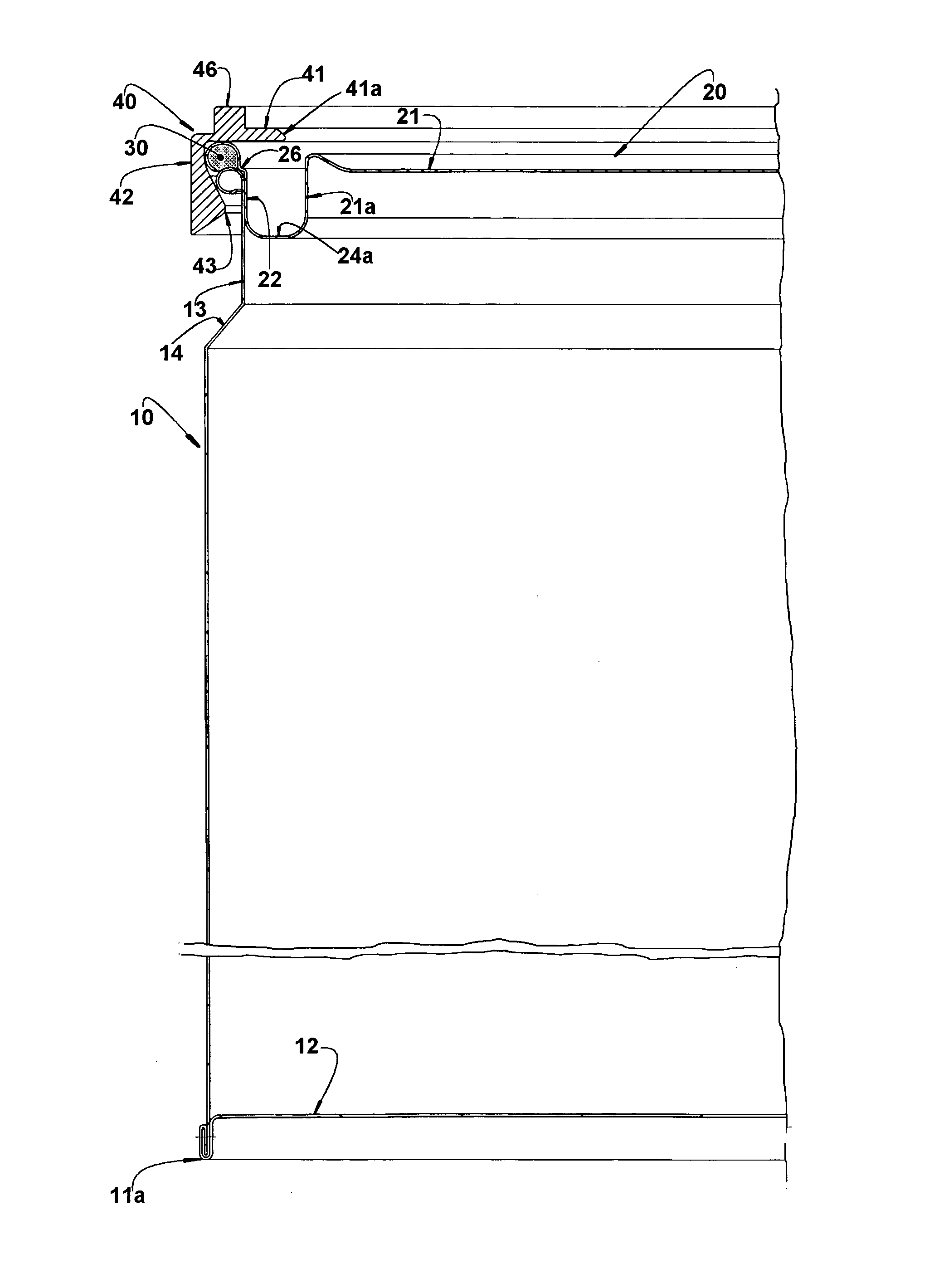
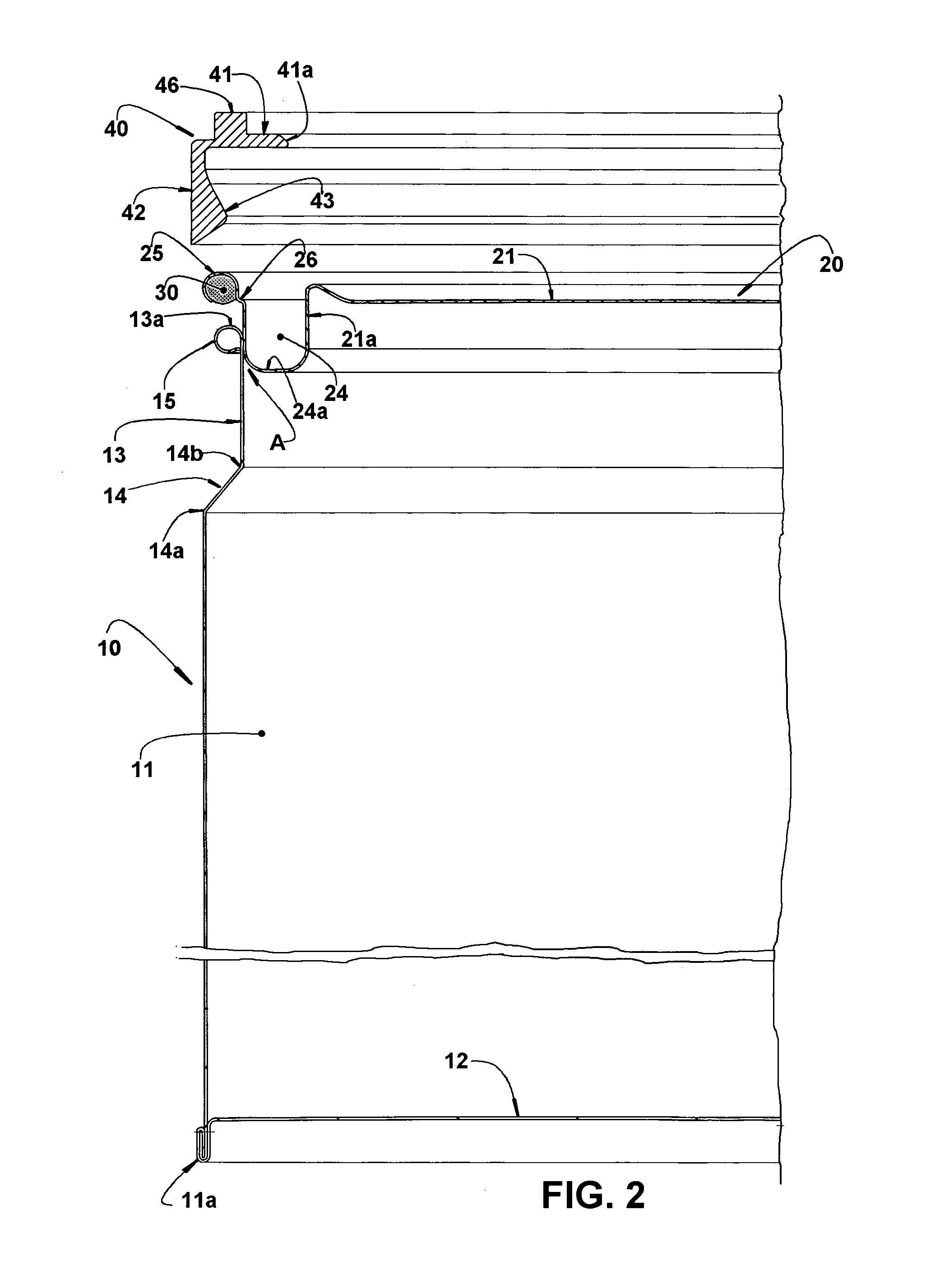
The present invention provides a closure arrangement for a can of the type described that is easy to use and reliable in terms of quality standards. The closure is designed to provide a high degree of tightness, even if there are variations in the dimensions of the can. The arrangement includes an annular gasket that is housed inside the lid and is pressed against the neck portion of the can to create a seal. This design prevents excessive deformation of the lid and ensures the proper fitting of the lid into the can.

Problems solved by technology

Without the annular upper wall, the thickness of the metallic sheet of the body portion would have to be considerably increased, with the consequent increase in the cost of the raw material and in the weight of the can.
In spite of the above-mentioned advantages for cans provided with a neck portion of reduced section and without an annular upper wall, this prior art construction presents the drawback of not guaranteeing a high and reliable tightness degree in the closure of the lid.
This constructive particularity usually affects, restrictively, the can structural resistance upon stacking.
Although the provision of said annular gasket provides an adequate tightness degree in the closure of the lid in the upper opening of the can, it leads to an undesirably complex and difficult to control operations for applying the gasket, in the form of a resin bead under the outer circumferential rib of the lid.
It is difficult to control the borders of the resin bead onto the lower convex surface of the outer circumferential rib of the lid, which fact impairs or even avoids obtaining a desired quality standard.

Method used


Image

  • Closure Arrangement for Cans
  • Closure Arrangement for Cans
  • Closure Arrangement for Cans

Examples


Embodiment Construction

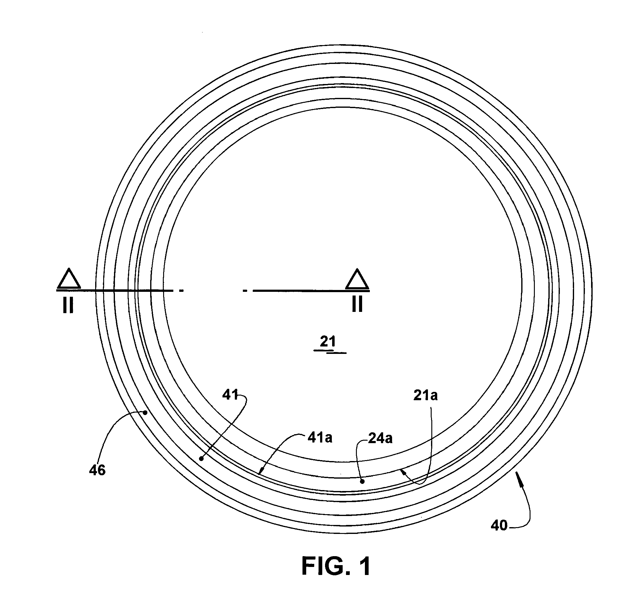
[0024]As already previously described and illustrated in the enclosed drawings, the closure arrangement proposed by the invention is applied to a can 10 formed in metallic sheet, generally tinplate, presenting a generally circular cross-section, but which can be polygonal, although not being illustrated in the drawings.

[0025]The tubular shaped can 10 comprises: a body portion 11, in whose lower end edge 11a is affixed, generally by double-seaming, the peripheral edge of a bottom wall 12; a neck portion 13 having a concentric contour, which is similar and reduced in relation to that of the body portion 11, and an upper end edge 13a defining the contour of an upper opening A for the can 10; and a transition portion 14 with a profile inclined in relation to the axis of the can 10 and joining the body portion 11 and the neck portion 13.

[0026]The upper end edge 13a of the neck portion 13 incorporates an outer peripheral projection 15. In the illustrated condition, the outer peripheral pr...


PUM


Abstract

The can of the invention includes a body portion joined to a neck portion of reduced contour and which incorporates an outer peripheral projection and which defines an upper opening; and a lid having a peripheral tubular portion to be fitted into the upper opening, and an outer circumferential rib. The outer circumferential rib presents a semi-tubular shape, inferiorly opened and having: a radially inner edge which is joined to the upper edge of the peripheral tubular portion of the lid, by an annular step; and a radially outer edge. The outer circumferential rib carries, in its interior, an annular gasket to be seated on the outer peripheral projection of the neck portion, upon the fitting of the lid into the upper opening and the seating of the annular step on said outer peripheral projection.

Description

FIELD OF THE INVENTION[0001]The present invention refers to a closure arrangement to be applied to cans formed in metallic sheet and comprising a tubular body portion, generally presenting a circular section and carrying a bottom wall, an upper neck portion with a contour smaller than that of the body portion, and a transition portion joining the body portion and neck portion and having an end edge which defines the contour of an upper opening for the can, on which is fitted a removable lid.PRIOR ART[0002]There are well known from the prior art the tubular cans obtained in metallic sheet and comprising a body portion, of circular or polygonal cross-section and carrying a bottom wall and an annular upper wall which are peripherally attached, generally by double-seaming, to the lower end edge and upper end edge of the can.[0003]This type of construction, which is well known in the art, allows the bottom wall and the annular upper wall to exert a function of structuring the body portio...

Claims


Application Information

Patent Timeline
IPC IPC(8): B65D1/02
CPCB65D43/022B65D2543/00092B65D2543/00277B65D2543/00509B65D2543/00972B65D45/30B65D1/023
Inventor ALVARES, ANTONIO CARLOS TEIXEIRASENE, ANTONIO ROBERTO
Owner BRASILATA S A EMBALAGENS METALICAS
Learn More