
Polarizing plate and optical display including the same

a technology of polarizing plate and optical display, which is applied in the direction of polarizing elements, instruments, optics, etc., can solve the problems of low yield, thick polarizing plate, and display may not be visibl

Active Publication Date: 2014-07-31
SAMSUNG SDI CO LTD
View PDF6 Cites 4 Cited by
  • Summary
  • Abstract
  • Description
  • Claims
  • Application Information

AI Technical Summary

Benefits of technology

The present invention relates to a polarizing plate and an optical display that includes the polarizing plate. The polarizing plate includes a polarizer and a protective film with a reverse dispersion liquid crystal coating layer. The technical effect of this invention is to provide a display with improved image quality and reduced color distortion caused by external light interference.

Problems solved by technology

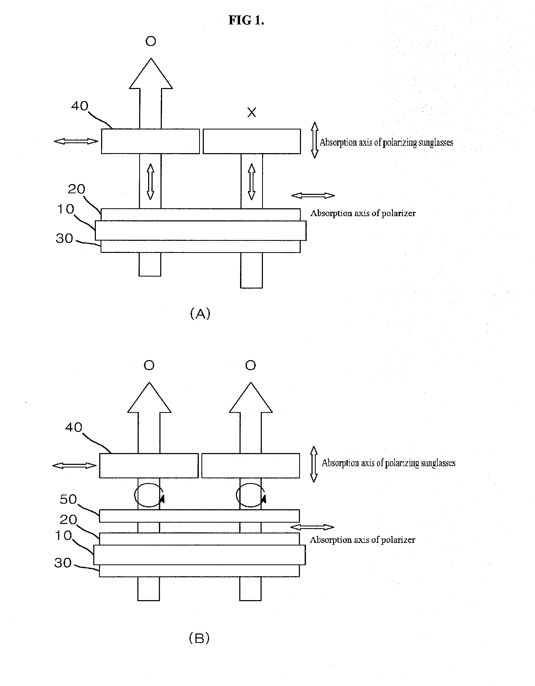
However, when a display panel including a polarizing plate is viewed through polarizing sunglasses, the screen of the display may not be visible due to the perpendicular alignment of the polarizing plate of the display panel and the polarizing film of the sunglasses.
However, the polarizing plate prepared in this manner is thick and has low yield.

Method used


Image

  • Polarizing plate and optical display including the same
  • Polarizing plate and optical display including the same
  • Polarizing plate and optical display including the same

Examples


example 1

[0063]A polarizer was prepared by dyeing of a material for polarizers, followed by stretching, and the like. Specifically, a polyvinyl alcohol film (PS60, Kuraray Co., Ltd., Japan, thickness: 60 μm) was stretched to 2 times its initial length at 50° C., followed by iodine adsorption onto the polyvinyl alcohol film, and stretching again to 2.5 times the length of the stretched film in a boric acid solution at 40° C., thereby preparing a polarizer (thickness: 22 μm).

[0064]A reverse dispersion liquid crystal coating layer (liquid crystals: nematic monomolecular liquid crystals, thickness: 3.5 μm, Re: 148 nm and Rth: 100 nm at a wavelength of 550 nm) was coated onto one surface of a protective film HC TAC (hard coating-triacetyl cellulose, DNP Co., Ltd., Japan, thickness: 30 μm) by die coating.

[0065]The HC TAC including the reverse dispersion liquid crystal coating layer formed thereon was stacked on an upper side of the polarizer such that the reverse dispersion liquid crystal coating ...

example 2

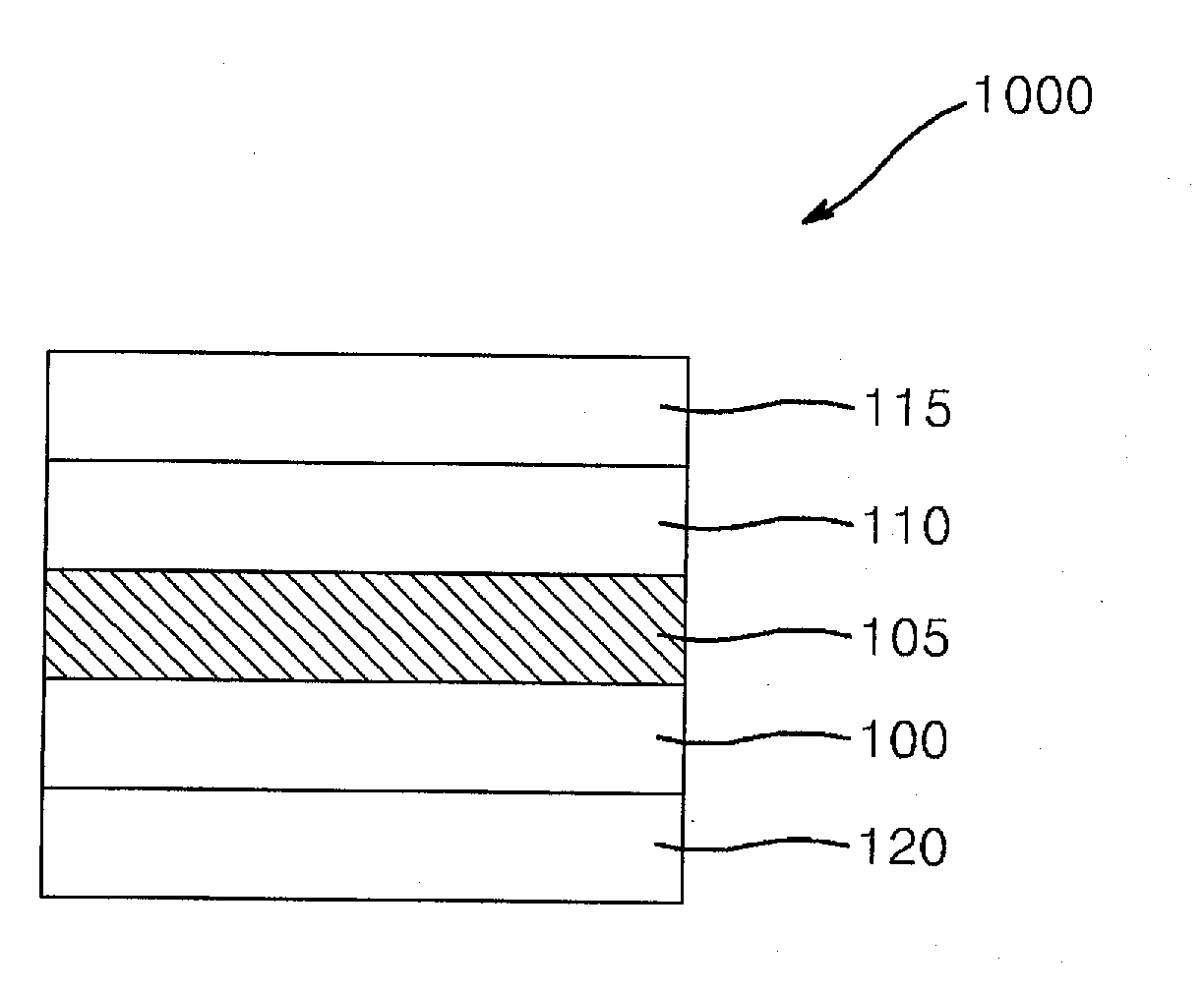
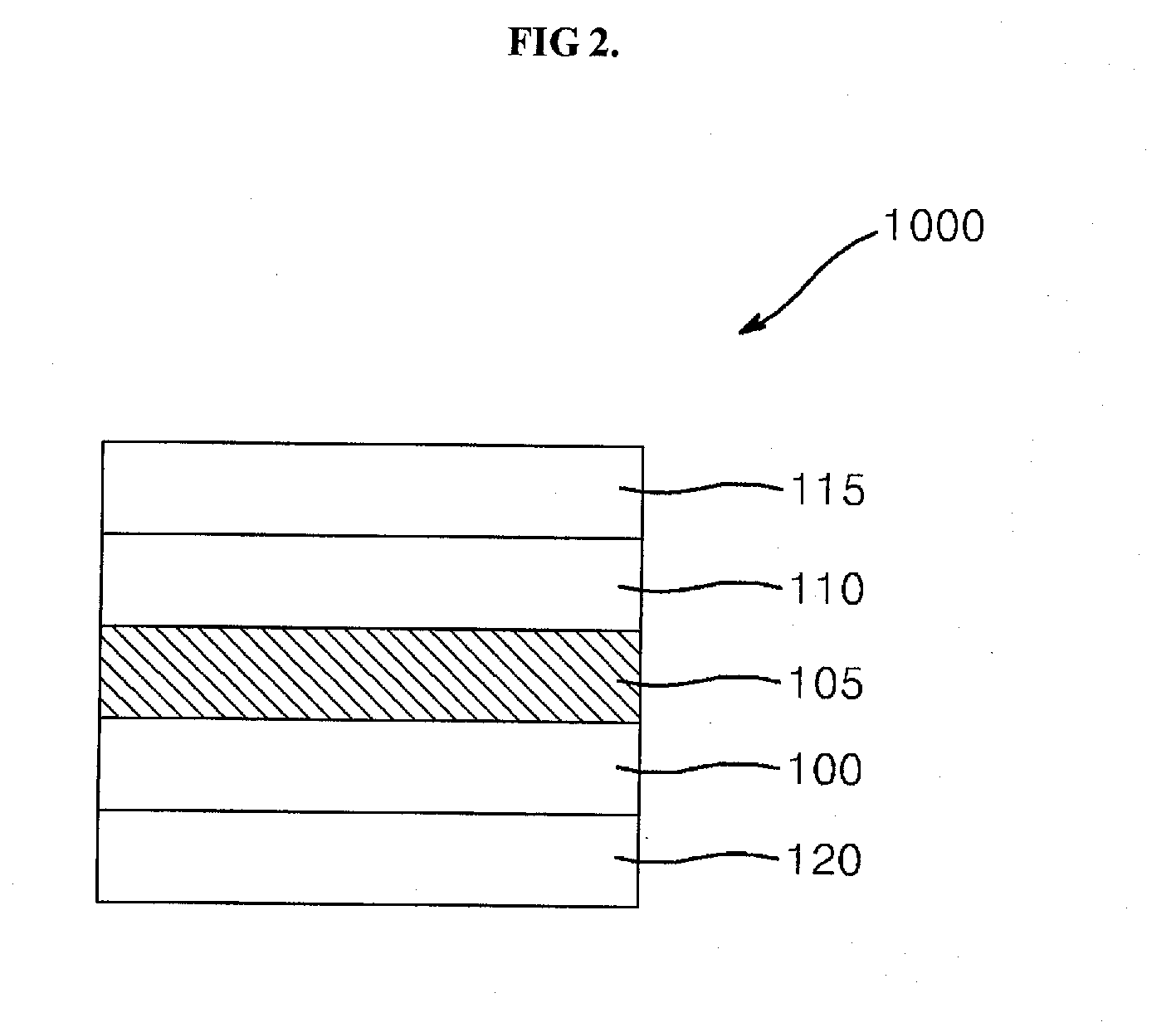
[0067]A polarizing plate having the structure shown in FIG. 3 was prepared in the same manner as in Example 1 except that a λ / 2 retardation layer (thickness: 43 μm, Re: 260 nm and Rth: 130 nm at a wavelength of 550 nm) was further formed between the HC TAC film (used as the protective film) and the reverse dispersion liquid crystal coating layer.


PUM

PropertyMeasurementUnit
thicknessaaaaaaaaaa
thicknessaaaaaaaaaa
thicknessaaaaaaaaaa

Abstract

A polarizing plate includes a polarizer, and a protective film on one side of the polarizer and including a reverse dispersion liquid crystal coating layer having λ / 4 retardation. An optical display panel includes the polarizing plate. The polarizing plate has a depolarization function and allows for viewing of the display panel through polarizing sunglasses.

Description

CROSS-REFERENCE TO RELATED APPLICATION[0001]This application claims priority to and the benefit of Korean Patent Application No. 10-2013-0011025, filed in the Korean Intellectual Property Office on Jan. 31, 2013, the entire content of which is incorporated herein by reference.BACKGROUND[0002]1. Field[0003]The following description relates to a polarizing plate and an optical display including the same.[0004]2. Description of the Related Art[0005]Polarizing sunglasses include a polarizing film which filters light from the outside by allowing only light incident at a certain angle to be visible. Generally, polarizing sunglasses are used during driving or fishing.[0006]However, when a display panel including a polarizing plate is viewed through polarizing sunglasses, the screen of the display may not be visible due to the perpendicular alignment of the polarizing plate of the display panel and the polarizing film of the sunglasses.[0007]FIG. 1(A) shows a display including a liquid crys...

Claims


Application Information

Patent Timeline
Patent Type & Authority Applications(United States)
IPC IPC(8): G02F1/1335
CPCG02F1/133528G02B5/3016G02F2001/133633G02F1/133633G02B5/30G02F1/1335
Inventor KIM, YONG, WOON
Owner SAMSUNG SDI CO LTD
Learn More