
Ignition system for flame emitting apparatus

a technology of ignition system and flame emitting device, which is applied in the direction of domestic stoves or ranges, heating fuel, domestic heating, etc., can solve the problems of false readings, affecting the operation of the flame sensor, and the prior ignition system experiencing difficulties in properly confirming

Inactive Publication Date: 2014-07-31
7794754 CANADA
View PDF7 Cites 26 Cited by
  • Summary
  • Abstract
  • Description
  • Claims
  • Application Information

AI Technical Summary

Benefits of technology

The present invention provides systems for detecting the presence of a flame in a flame-emitting apparatus. The system includes a temperature sensor positioned near the flame and a controller that analyzes the sensor's data to determine if a flame is present and can interrupt the supply of fuel to the burner if one is not. The system can be used in cooking apparatuses, such as rotisserie ovens or grills, where a flame plays a crucial role in the cooking process. The control system is designed to ensure efficient combustion of fuel and minimize energy waste.

Problems solved by technology

Prior ignition systems experience difficulties in properly confirming that a flame is present when initially igniting the burner or confirming a flame continues to be present during operation of the oven.
The flame sensor can become fouled and rendered inoperable.
Because of limitations in the structure and methods of such prior art systems, false readings can occur or the system can experience the inability to obtain a reading to confirm the presence of a flame.
Thus, while flame detecting systems according to the prior art provide a number of advantageous features, they nevertheless have certain limitations.

Method used


Image

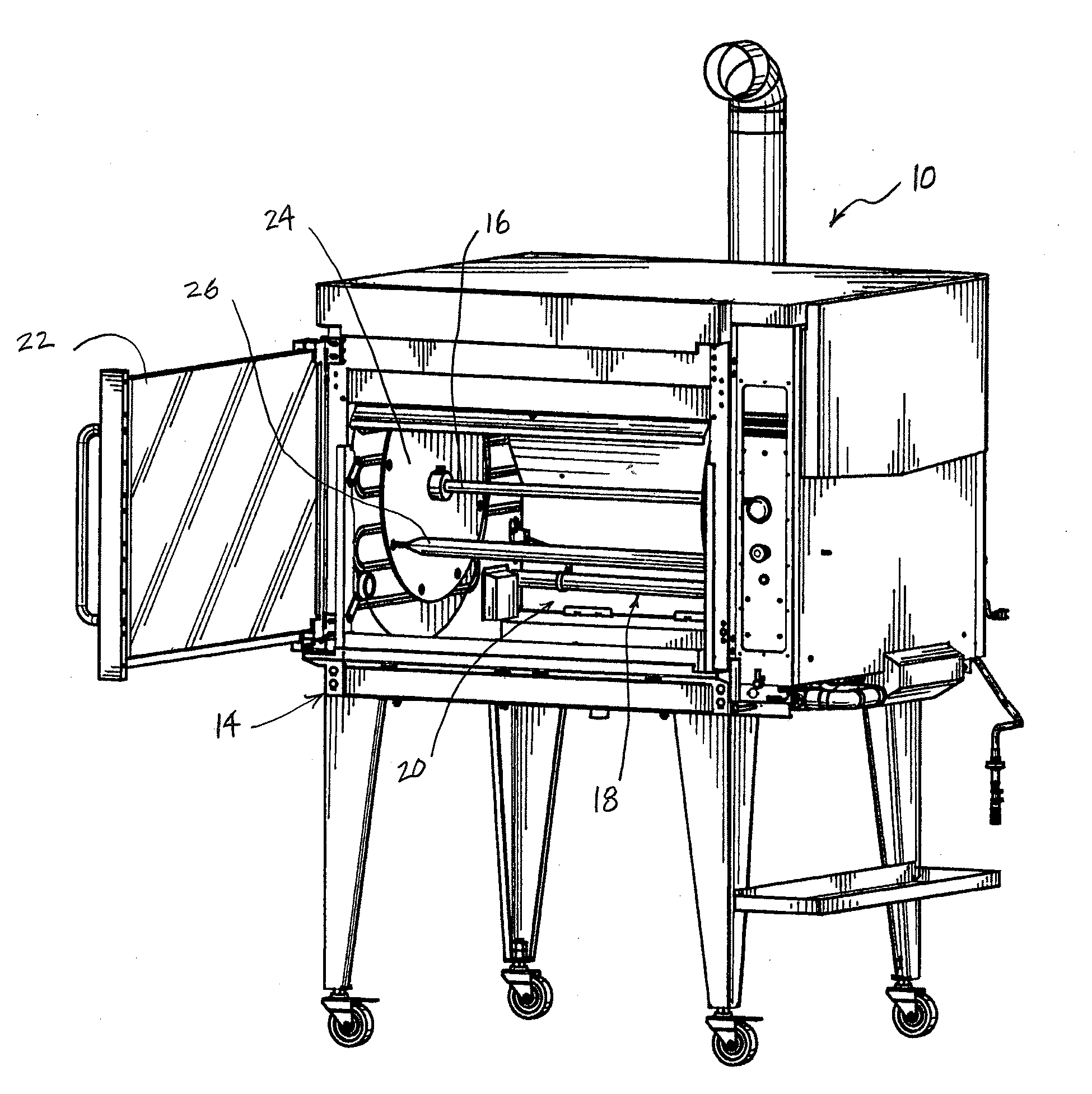
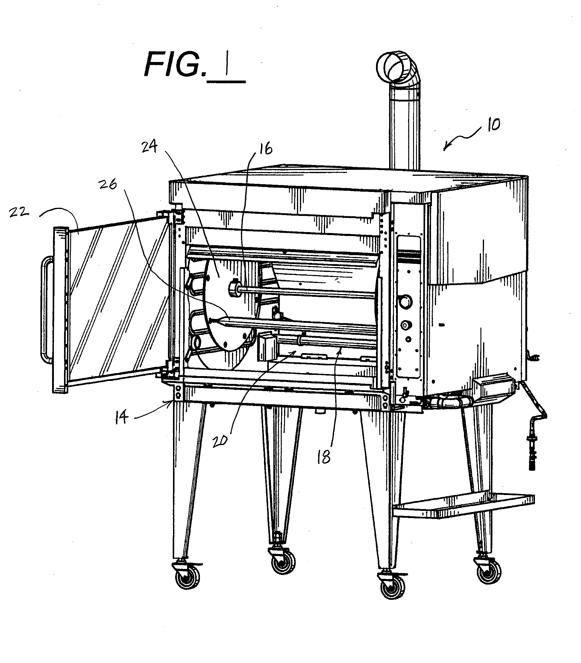
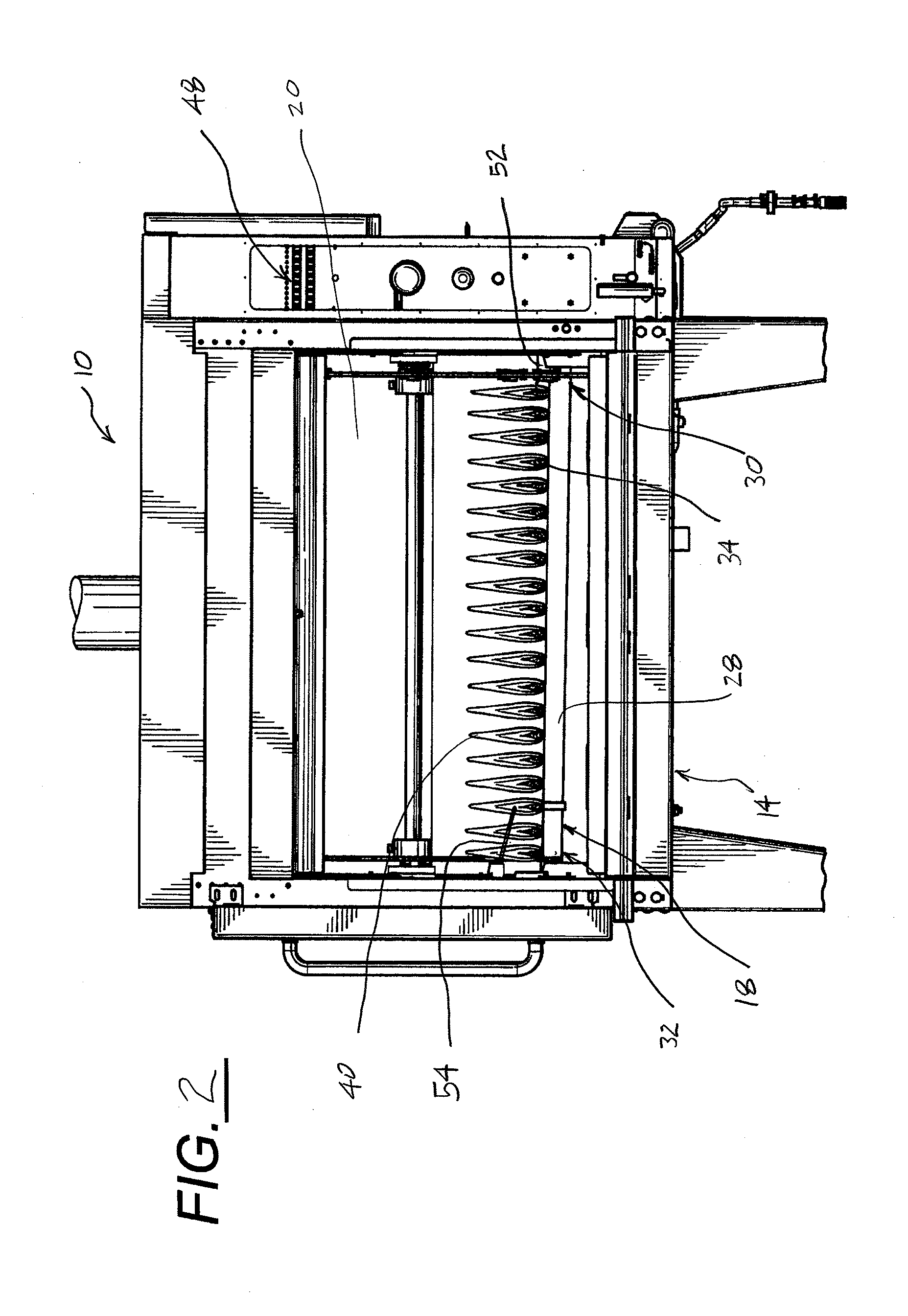
  • Ignition system for flame emitting apparatus
  • Ignition system for flame emitting apparatus
  • Ignition system for flame emitting apparatus

Examples


Embodiment Construction

[0028]While this invention is susceptible of embodiment in many different forms, there is shown in the drawings, and will herein be described in detail, preferred embodiments of the invention with the understanding that the present disclosure is to be considered as an exemplification of the principles of the invention and is not intended to limit the broad aspect of the invention to the embodiments illustrated.

[0029]The present invention relates generally to a variety of flame-emitting apparatuses including cooking apparatuses. A flame-emitting apparatus typically has some form of burner connected to a fuel source. The apparatus also may have an ignition system for initially igniting the fuel supplied to the burner. The present invention includes structures and methods that confirm the presence of a flame upon igniting the burner to assure proper operation. Such structures and methods may be an integral part of the ignition system or operably interact with the ignition system, and m...


PUM


Abstract

A flame-emitting apparatus is provided, whereby a burner has an inlet connected to a fuel source. Fuel burned by the burner provides a flame extending from an outlet of the burner. A flame ignition system detects the presence of the flame during operation of the apparatus and controls supply of fuel to the burner in response to flame detection.

Description

CROSS-REFERENCE TO RELATED APPLICATIONS[0001]The present application is a Continuation application and claims the benefit of U.S. patent application Ser. No. 13 / 101,821, filed on May 5, 2011, currently pending, which in turn claimed the benefit of priority to U.S. Provisional Patent Application. No. 61 / 331,702 filed May 5, 2010, expired, both of which are incorporated by reference herein and made a part hereof.BACKGROUND OF THE INVENTION[0002]1. Field of the Invention[0003]The present invention generally relates to an ignition system for a flame-emitting apparatus and more particularly to an ignition system for a cooking apparatus such as a rotisserie oven that confirms the presence of a flame.[0004]2. Background of the Invention[0005]Several types of apparatuses emit flames such as cooking apparatuses, heating lamps, gas lamps used for lighting and other decorative appliances. For operation of these apparatuses, a flame is ignited from a fuel source such as propane or natural gas. ...

Claims


Application Information

Patent Timeline
IPC IPC(8): F23N5/24F23N5/10
CPCF23N5/242F23N5/102F23N5/203F24C3/087F24C3/103F23N2227/02F23N2229/00F23N2241/08
Inventor BANU, CRISTIAN MITORIDEFOY, JEAN FRANCISFRIEDMAN, NITAI
Owner 7794754 CANADA
Learn More