Method and apparatus of detecting fire by flame imaging

a flame imaging and apparatus technology, applied in the direction of fire alarms, optical radiation measurement, instruments, etc., can solve the problems of flame image analysis being subject to false alarms, and being particularly troublesome in reflections

Inactive Publication Date: 2006-12-26
DETECTOR ELECTRONICS CORP
View PDF28 Cites 25 Cited by
  • Summary
  • Abstract
  • Description
  • Claims
  • Application Information

AI Technical Summary

Benefits of technology

[0011]It is the purpose of the claimed invention to overcome these difficulties, thereby providing an improved apparatus and method for detecting fires by flame imaging.

Problems solved by technology

A significant disadvantage of such detectors is that they are subject to false alarms, as many non-flame sources also produce infrared and ultraviolet light in the same wavelength bands.
One source of false alarms that is particularly troublesome is that of reflections.
However, as with individual sensors, flame image analysis is often subject to false alarms.
Indeed, known flame imaging systems often may be more susceptible to false alarms than individual sensors.
A further problem with conventional flame image systems is that the image settings appropriate for flame imaging are not appropriate viewing non-flame images.
However, at such image settings the remaining (non-flame) portion of the image can be so dark that almost nothing can be seen in it.
In particular, objects and persons that may be distant from the flame cannot normally be identified, either by humans or by data processing routines.
As a result, an image optimal for flame detection is not optimally suited for other purposes, in particular human viewing, because practically nothing but the flames can be distinguished.
These images reveal little or no structure or color within the flame itself, thus limiting meaningful analysis.
Indeed, at such settings it can be difficult even to determine whether a bright spot is a fire at all, or whether it is some other bright phenomenon such as reflected sunlight or an incandescent bulb.
However, analysis of a single image does not yield any information related to changes in the image over time.
Such analysis is not possible with only a single image.

Method used


Image

  • Method and apparatus of detecting fire by flame imaging
  • Method and apparatus of detecting fire by flame imaging
  • Method and apparatus of detecting fire by flame imaging

Examples


Embodiment Construction

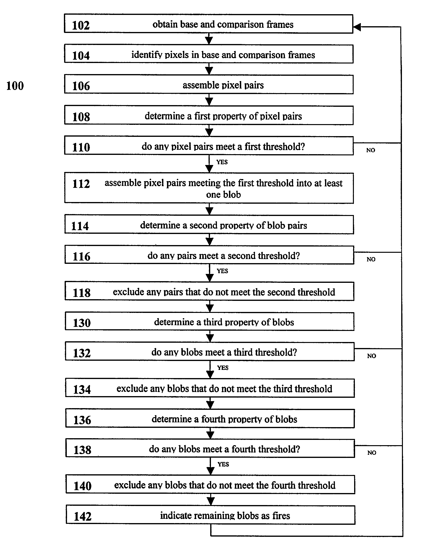
[0080]As noted previously, an apparatus 10 in according with the principles of the claimed invention is adapted to generate at least two first frames and a plurality of second frames, and to contemporaneously perform first and second processes therewith.

[0081]Referring to FIG. 1, an apparatus 10 in accordance with the principles of the claimed invention includes a video sensor 12. In a preferred embodiment of the apparatus, the video sensor 12 is a conventional digital video camera. This is convenient, in that it enables easy communication with common electronic components. However, it will be appreciated by those knowledgeable in the art that this choice is exemplary only, and that a variety of alternative video sensors 12 may be equally suitable, including but not limited to analog video cameras. In a preferred embodiment, the video sensor 12 is a color video sensor 12, adapted for obtaining color image, i.e. images that distinguish between different wavelengths of light. However,...


PUM


Abstract

An apparatus and method for performing first and second imaging processes contemporaneously, in particular where one of the processes is detecting fires based on images of the flames. The apparatus includes an image sensor for producing a video image, a frame grabber for capturing first frames and second frames, a processor for processing the data within the frames, and an output device. The apparatus may also include an adjustment mechanism for adjusting the image settings of the image sensor between settings suitable for flame imaging and non-flame imaging, and a control mechanism for controlling the image settings of the image sensor. In the method at least two first frames are obtained, and a plurality of second frames are obtained. The first and second frames are used for first and second processes. The first and second processes are contemporaneous, so that they are carried out within the same time period without interfering with one another. When the first process is flame detection, individual pairs of pixels having a property such as intensity that meets a first threshold are identified within the first frames, and are assembled into blobs. Additional properties of the pixel pairs and the blobs overall are evaluated in relation with additional thresholds. Blobs or pixels that do not meet the thresholds are excluded. Any blobs remaining after all evaluations are considered fires.

Description

BACKGROUND OF THE INVENTION[0001]This invention relates to an apparatus and method for detecting fires by analysis of images of potential flames.[0002]Fires emit a range of wavelengths. The art of optical fire detection is based upon sensing types of light that are characteristic of fires. More sophisticated detectors also analyze the light to exclude possible false alarms.[0003]It is well known to use one or several individual sensors in a fire detector. Typically the sensors are sensitive to particular infrared and / or ultraviolet wavelength bands of light that are known to be present in most fires.[0004]A significant disadvantage of such detectors is that they are subject to false alarms, as many non-flame sources also produce infrared and ultraviolet light in the same wavelength bands. Common false alarm sources include but are not limited to artificial lighting, sunlight, and arc welding. One source of false alarms that is particularly troublesome is that of reflections. Reflect...

Claims


Application Information

Patent Timeline
Patent Type & Authority Patents(United States)
IPC IPC(8): G06K9/00G08B17/12
CPCG08B17/125
Inventor KING, JOHN D.JUNCK, PAUL M.
Owner DETECTOR ELECTRONICS CORP
Why Eureka
Try Eureka