Helmet systems and other wearable safety gear

a technology of helmets and helmets, applied in the field of helmets, can solve the problems of slow helmet speed and helmets moving away from each other, and achieve the effect of reducing head trauma and reducing the force that causes head trauma

Inactive Publication Date: 2014-08-07
OGARA GREGORY J
View PDF28 Cites 28 Cited by
  • Summary
  • Abstract
  • Description
  • Claims
  • Application Information

AI Technical Summary

Benefits of technology

[0003]The present invention exploits magnetic force, in a helmet system, to reduce head trauma, such as in a helmet system using magnetic force to reduce forces that cause head trauma. Helmets repel when magnetic materials are aligned or arranged to create a repulsive force between two helmets, such as by exploiting a front repulsive forc

Problems solved by technology

This slows the velocities of the helmets, deflects the helmets as the

Method used


Image

  • Helmet systems and other wearable safety gear
  • Helmet systems and other wearable safety gear
  • Helmet systems and other wearable safety gear

Examples


example 1

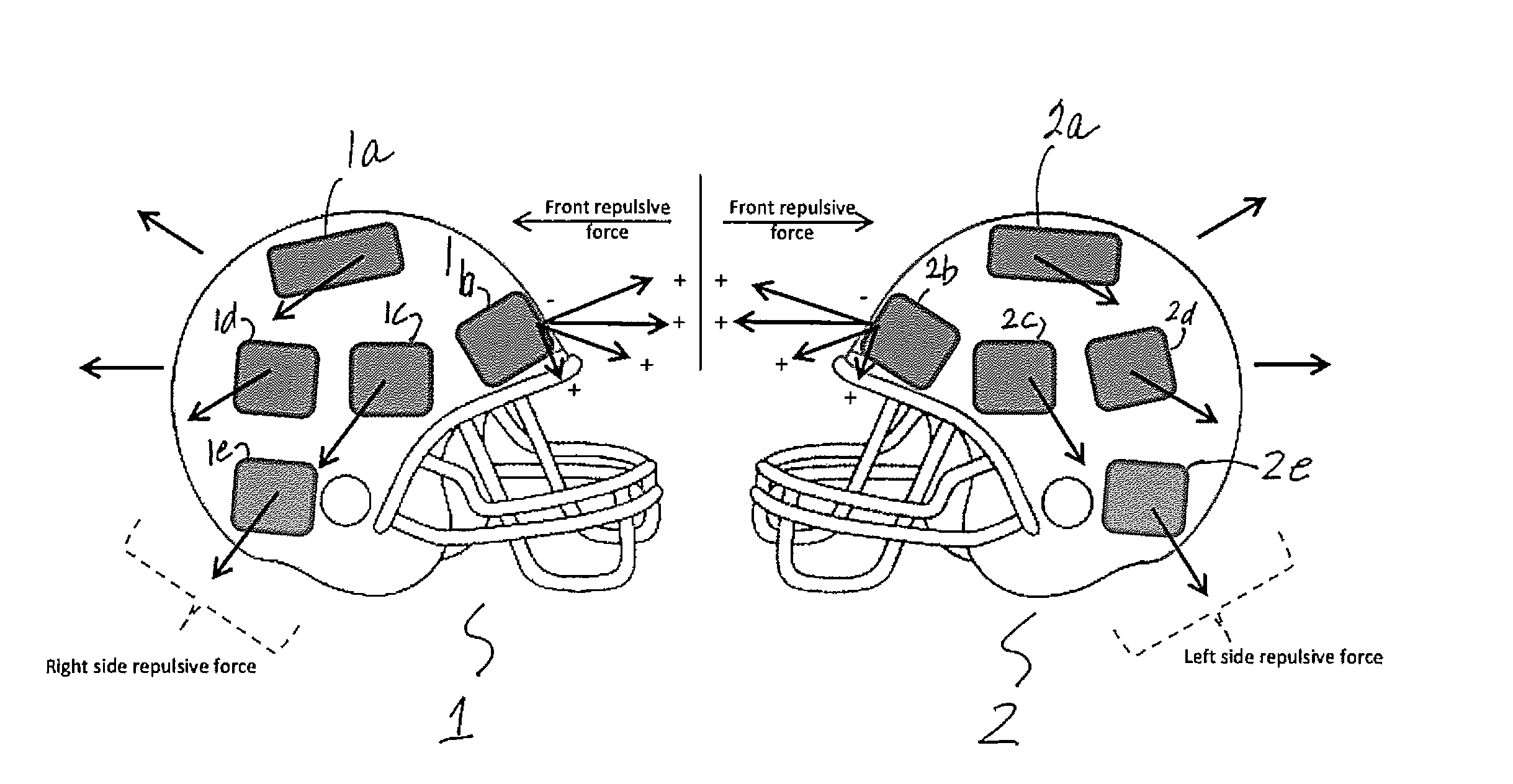
[0045]Referring to FIG. 1, wearable gear 1, 2 each is illustrated as a helmet which is a preferred example of wearable gear. It should be appreciated that wearable gear 1, 2 is not limited to a helmet. Examples of wearable gear 1, 2 are, e.g., a helmet (such as, e.g., a football helmet), a knee pad, etc.

[0046]Wearable gear 1 comprises magnetic materials 1a, 1b, 1c, 1d, 1e. Wearable gear 2 comprises magnetic materials 2a, 2b, 2c, 2d, 2e.

example 2

Optional Controller

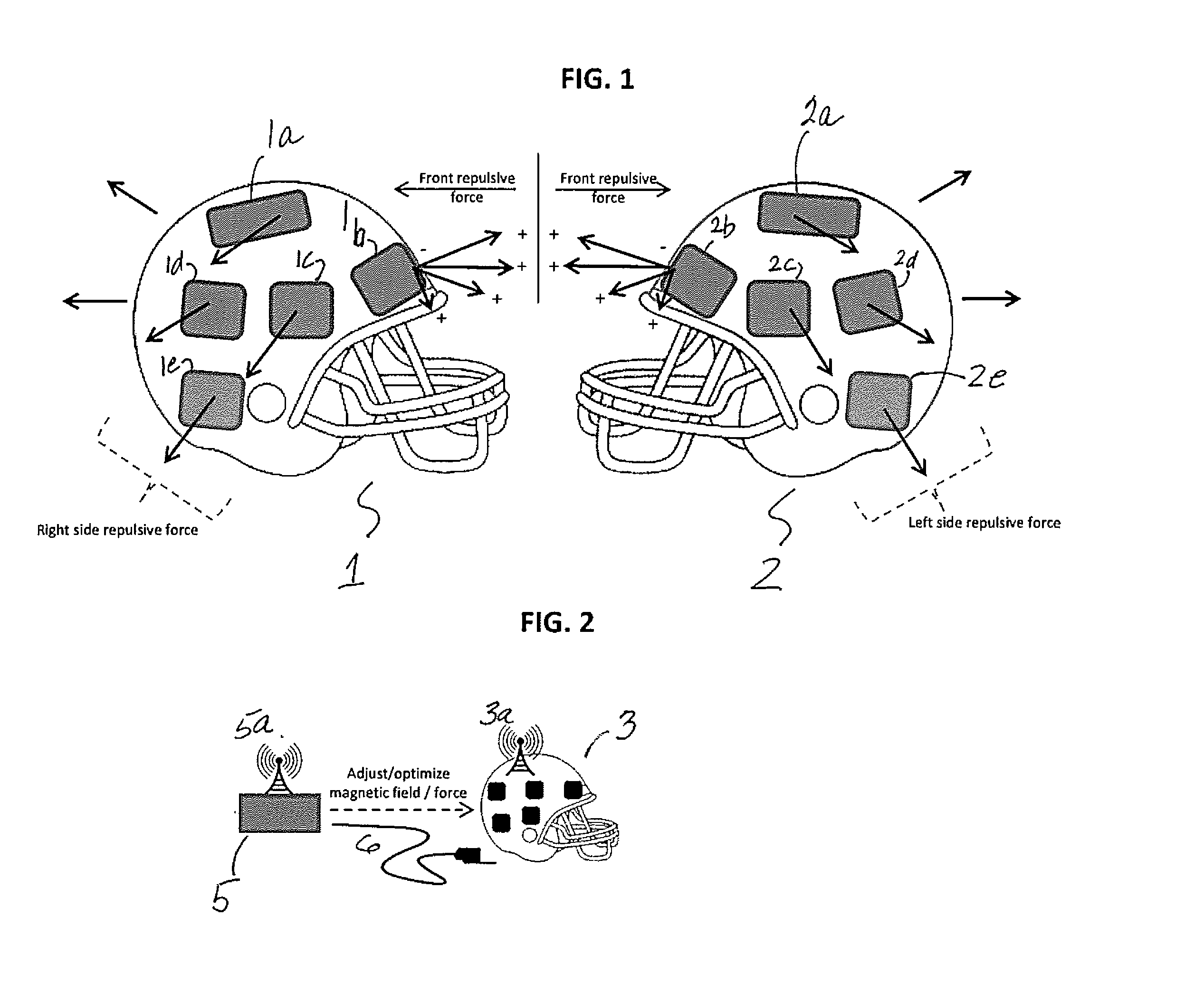
[0047]In this example, referring to FIG. 2, an optional controller 5 is a separate unit that connects to each helmet 3 and adjusts the magnetic material in each helmet 3 to optimize the repulsive magnetic field before collisions. Controller 5 is in a form of a controller box that connects to helmet 3 via a connection (such as, e.g., a connection through transmitter 5a / receiver 3a; a direct hardwire connection 6).

[0048]A processor or other computer performs a step of informing the controller box of the optimal magnetic fields in each helmet 3 to minimize concussive forces. A processor or other computer tracks the position of each helmet 3, relative speed, and adjusts the magnetic fields in each helmet 3 to optimize their repulsive magnetic forces to reduce concussive force and injury to a player wearing helmet 3.

example 3

Velocity Reduction and Deflection in Helmets with Repelling Magnetic Fields

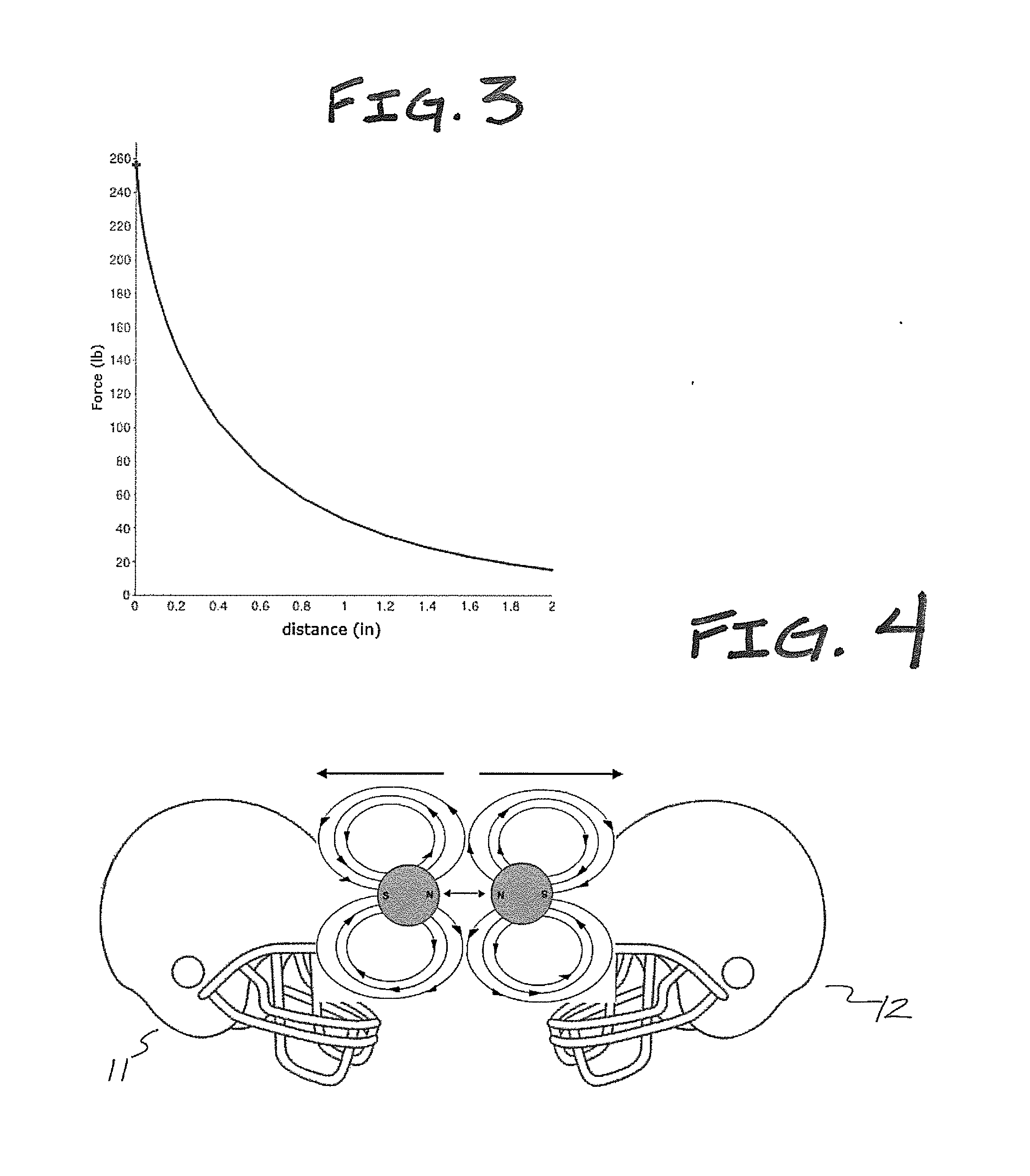
[0049]To decrease head trauma caused by football helmet collisions, the impact force associated with hits to the head is decreased. Two ways of accomplishing such decrease in impact force are:

[0050]1. Decrease the amount of energy transferred during the collision;

[0051]2. Increase the amount of time it takes to transfer the energy.

Decrease of energy transfer during the collision and increase of time to transfer energy are NOT mutually exclusive, and in the invention, preferably both approaches are used simultaneously or in combination.

[0052]Decreasing the Energy Transfer.

[0053]The amount of energy transferred is a function of the component of the relative velocity normal to the surface of helmets at the point of impact. This can be readily seen by considering elastic collisions of spherical bodies. It follows that we can decrease the amount of energy transferred by decreasing this component of the player's re...


PUM


Abstract

A system of two or more helmets used in team sports with magnetic material embedded in, or attached to, each helmet. Magnets are positioned identically in helmets so that the north magnetic field is facing outward. When two or more helmets come in close proximity, the like magnetic fields repel one another. This slows the velocities of the helmets, deflects the helmets as they collide, and generally causes helmets to move away from one another. This system is applicable for any sport or activity where concussive forces are caused by two or more helmets colliding, such as helmets in football, hockey, lacrosse, etc. When the helmet system is in place, magnets polarized in the same direction can be placed in other team equipment (e.g., knee pads) to mitigate blows to the head caused by that part of the body.

Description

FIELD OF THE INVENTION[0001]The invention relates to wearable safety gear, especially helmet systems and helmets worn by athletes.BACKGROUND OF THE INVENTION[0002]Football players (including high school students, college students, professional players, etc.) currently suffer certain injuries, especially concussions and head trauma, despite their wearing of currently-available safety gear. Reducing the instances of head trauma, and reducing the severity of head injuries, suffered by football players would be desirable.SUMMARY OF THE INVENTION[0003]The present invention exploits magnetic force, in a helmet system, to reduce head trauma, such as in a helmet system using magnetic force to reduce forces that cause head trauma. Helmets repel when magnetic materials are aligned or arranged to create a repulsive force between two helmets, such as by exploiting a front repulsive force that is produced by diametrically opposed magnetic material on two helmets. For example, magnetic materials ...

Claims


Application Information

Patent Timeline
IPC IPC(8): A42B3/04
CPCA42B3/0406A42B3/069
Inventor O'GARA, GREGORY J.
Owner OGARA GREGORY J
Why Eureka
Try Eureka