Flow meter with protruding transducers

a flow meter and transducer technology, applied in the field of ultrasonic flow meter, can solve the problems of difficult fabrication and mounting of the transducer inserts, affecting the accuracy, and interfering with the measurement, so as to reduce the cost of manufacturing, alleviate the effect of one, and eliminate the effect of the other

Active Publication Date: 2014-08-07
KAMSTRUP
View PDF5 Cites 25 Cited by
  • Summary
  • Abstract
  • Description
  • Claims
  • Application Information

AI Technical Summary

Benefits of technology

[0008]It would be advantageous to achieve an alternative to known flow meters which does not suffer from air bubbles attaching to the transducers, and which is cost-effect...

Problems solved by technology

Air pockets in the pipe system need not be a problem, however for ultrasonic flow meters there is a risk that the air pockets interfere with the ultrasonic signal path and thereby interfere with the measurement and affect the accuracy.
This is particularly a problem if the transducers reside at the hig...

Method used


Image

  • Flow meter with protruding transducers
  • Flow meter with protruding transducers
  • Flow meter with protruding transducers

Examples


Embodiment Construction

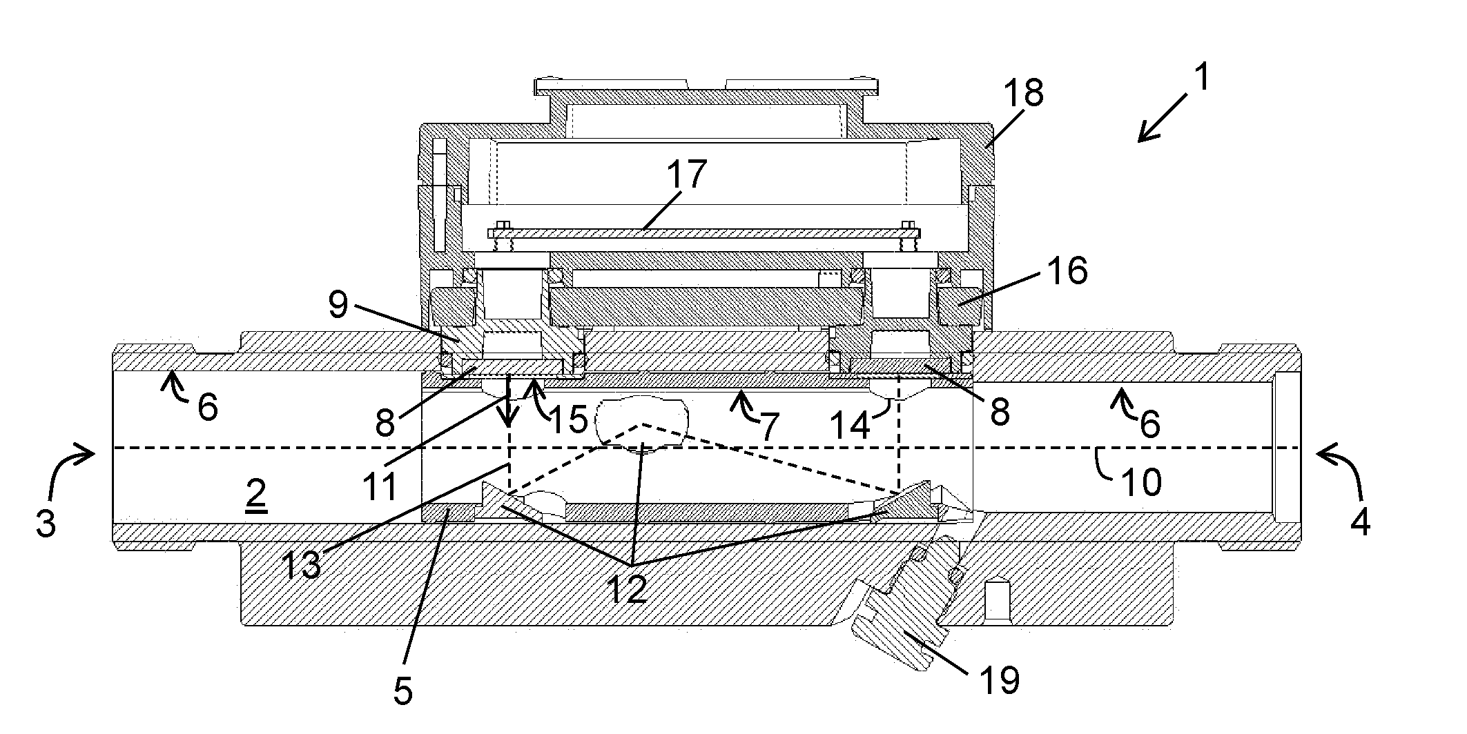
[0024]FIG. 1 illustrates an ultrasonic flow meter 1 known in the art. The figure illustrates the flow meter in a schematic cross-sectional view.

[0025]The flow meter comprises a through-going flow tube 2 arranged for passage of a liquid between an inlet 3 and an outlet 4, the flow tube defines a centre axis 10 between the inlet and the outlet. The flow tube comprises a measurement insert 5 which is inserted into the flow tube from one of the ends. The measurement insert is a plastic holder holding a number of mirrors 12, here three, for directing the ultrasonic signal 13 from an emitting transducer 8, through the flow tube to the receiving transducer 8. The flow tube defines a flow passage with an inner wall. The inner wall is defined by a combination of the inner wall 6 of the flow tube itself and an inner wall 7 of the measurement insert inserted into the flow tube.

[0026]The flow meter comprises two ultrasonic transducers 8, each being arranged in separate transducer inserts 9 whic...


PUM


Abstract

The invention relates to an ultrasonic flow meter arranged to measure a flow rate of a liquid, the flow meter comprises a flow tube 2, optionally a measurement insert, and two or more ultrasonic transducers 8 which are arranged in transducer inserts 20 to be inserted into the flow tube through openings in the flow tube. The transducer inserts are formed monolithically with the housing as a part of the bottom of the housing. The transducer inserts are in a mount position inserted through the openings in the flow tube to extend into the flow passage so that the surface 15 of the transducer inserts protrude into the flow passage. In this manner, gas bubbles, such as air bubbles, released from the flowing liquid will not rest in front of the transducer insert irrespectively of the orientation of the flow meter in the pipe installation.

Description

FIELD OF THE INVENTION[0001]The present invention relates to an ultrasonic flow meter arranged to measure a flow rate of a liquid, and in particular to a flow meter which is not sensitive to air bubbles attaching to the transducers during operation when mounted in a pipe installation.BACKGROUND OF THE INVENTION[0002]In an ultrasonic flow meter, ultrasonic transducers emit ultrasonic signals into a flowing medium in order to measure the flow rate, or other parameters, of the flowing medium. Flowing liquids may contain gas bubbles, in particular air bubbles, which are continuously released from the liquid and into the pipe system. The released air bubbles reside in the pipe system as air pockets in cavities of the pipe system for a period of time until they are flushed away by the flowing liquid.[0003]Ultrasonic flow meters installed in a pipe system may provide cavities in which released air can rest for a period of time. Air pockets in the pipe system need not be a problem, however ...

Claims


Application Information

Patent Timeline
IPC IPC(8): G01F1/66
CPCG01F1/66G01F1/667G01F1/662
Inventor NIELSEN, SOREN TONNESLAURSEN, PETER SCHMIDTSORENSEN, JENS LYKKE
Owner KAMSTRUP
Why Eureka
Try Eureka