Image device and imaging method

Active Publication Date: 2014-08-07
OM DIGITAL SOLUTIONS CORP
View PDF3 Cites 59 Cited by
  • Summary
  • Abstract
  • Description
  • Claims
  • Application Information

AI Technical Summary

Benefits of technology

[0006]An object of the present invention is to provide an imaging device and imaging

Problems solved by technology

An image sensor performs photoelectric conversion on an optical image and outputs image signals, but imaging noise

Method used


Image

  • Image device and imaging method
  • Image device and imaging method
  • Image device and imaging method

Examples


Embodiment Construction

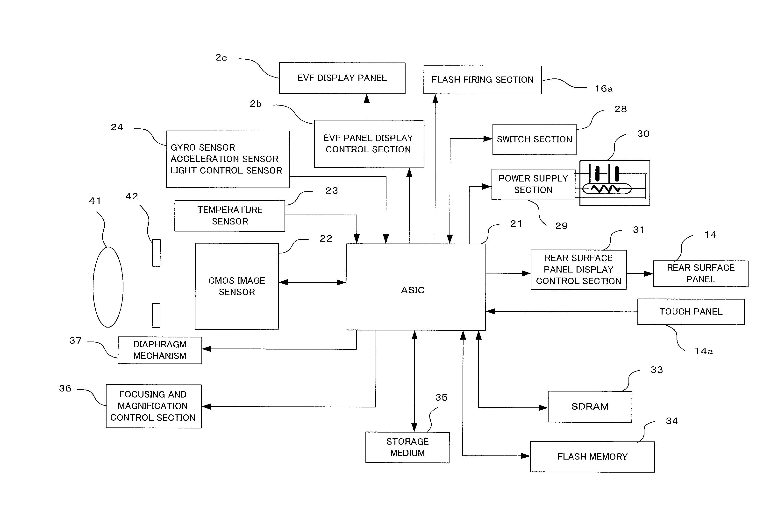
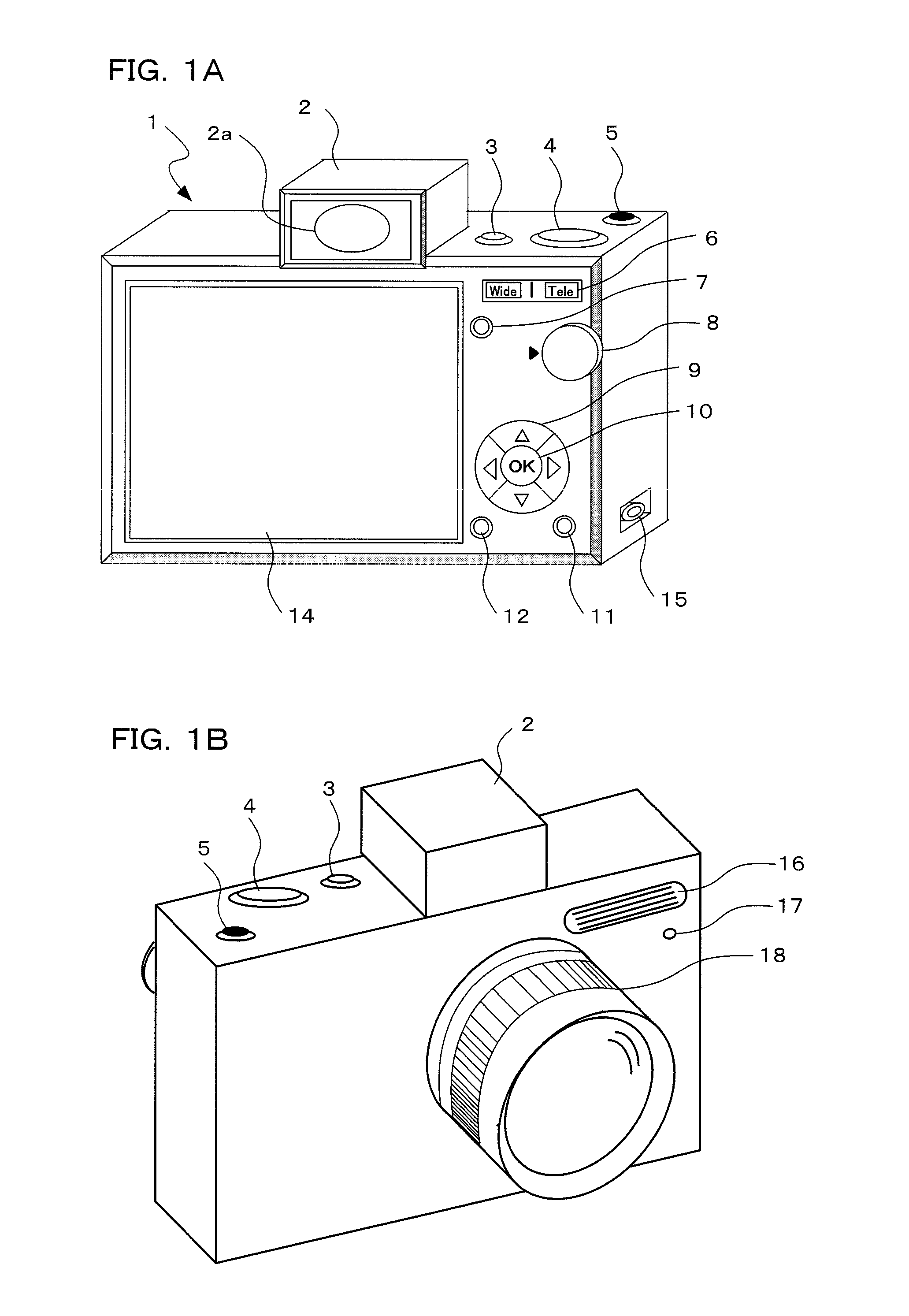
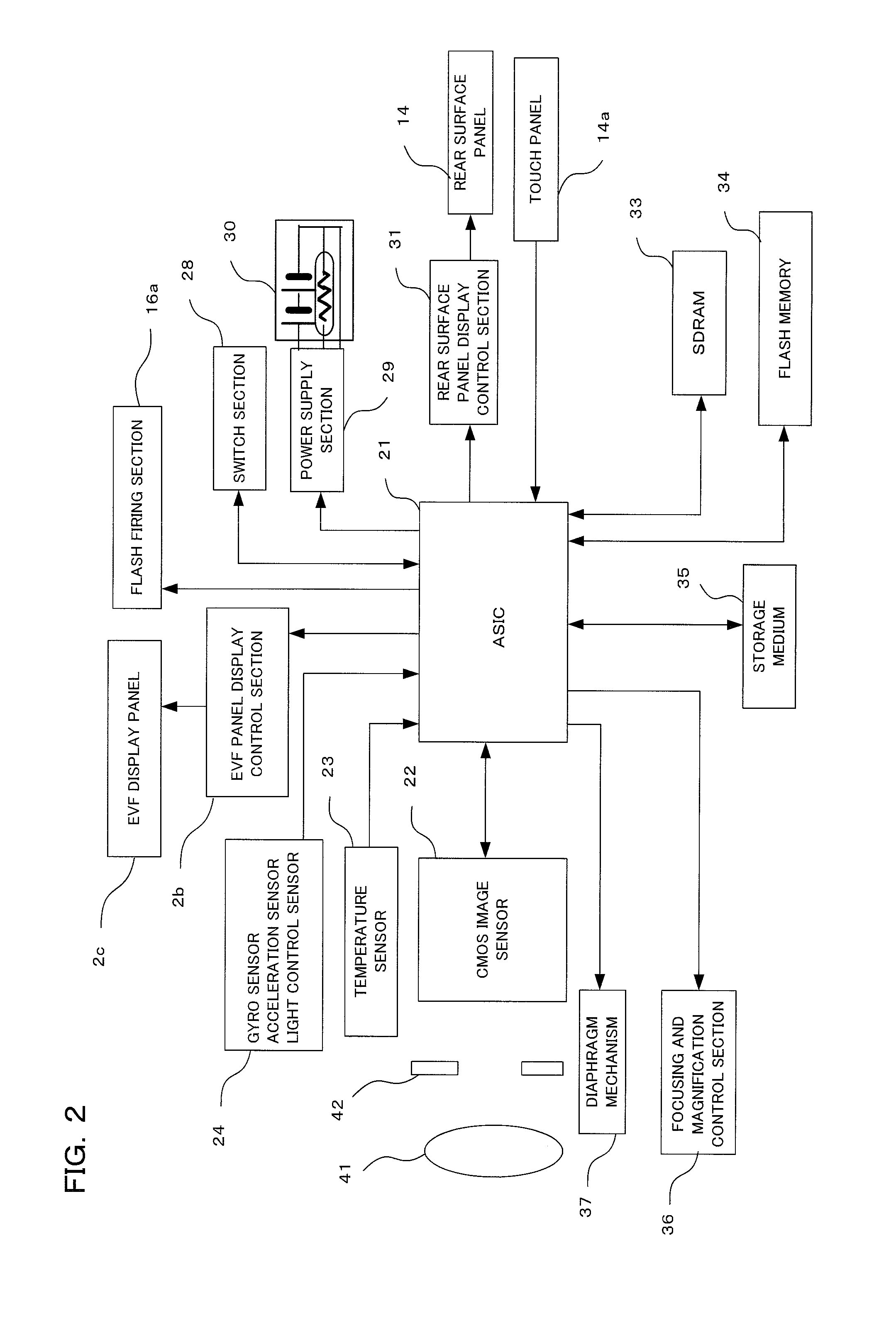
[0026]Preferred embodiments using a camera to which the present invention has been applied will be described in the following in accordance with the drawings. The camera of a preferred one embodiment of the present invention is a digital camera. This camera has an imaging section, with a subject image being converted to image data by this imaging section, and the subject image being subjected to live view display on a display section arranged on the rear surface of the camera body based on this converted image data. A photographer determines composition and photo opportunity by looking at the live view display. At the time of a release operation, still picture image data is stored in a storage medium. Image data that has been stored in the storage medium can be played back and displayed on the display section if playback mode is selected.

[0027]Also, this camera is operated by supply of power from a main power supply. A constant voltage is supplied to the imaging section from a varia...


PUM


Abstract

An imaging device of the present invention operates with supply of power from a main power supply, and comprises an imaging section having an image sensor for forming a subject image and outputting image data, a variable voltage conversion section, supplied with power from the main power supply, for converting to a designated voltage based on control signals, and outputting the designated voltage, a constant voltage section that receives output of the variable voltage conversion section and supplies a constant voltage signal to the image sensor, a noise level prediction section for predicting and outputting a noise level of image data of the image sensor, and a control section for calculating a voltage value input to the constant voltage section in accordance with output from the noise level prediction section, and designating an output voltage to the variable voltage conversion section.

Description

[0001]Benefit is claimed, under 35 U.S.C. §119, to the filing date of prior Japanese Patent Application No. 2013-021997 filed on Feb. 7, 2013. This application is expressly incorporated herein by reference. The scope of the present invention is not limited to any requirements of the specific embodiments described in the application.BACKGROUND OF THE INVENTION[0002]1. Field of the Invention[0003]The present invention relates to an imaging device and an imaging method, and in detail relates to an imaging device and an imaging method for supplying a constant voltage from a main power supply to an imaging section via a power supply section.[0004]2. Description of the Related Art[0005]An image sensor performs photoelectric conversion on an optical image and outputs image signals, but imaging noise occurs in the image accompanying increase in ambient temperature of the image sensor, which degrades image quality. In order to prevent this imaging noise, in Japanese patent laid open number 2...

Claims


Application Information

Patent Timeline
IPC IPC(8): H04N5/232
CPCH04N5/23241H04N23/65H04N23/667H04N23/69H04N25/63H04N25/709
Inventor NAKAMURA, SATORU
Owner OM DIGITAL SOLUTIONS CORP
Why Eureka
Try Eureka