Lighting device and cove lighting module using the same

a technology of lighting module and light source, which is applied in the direction of lighting and heating apparatus, planar/plate-like light guides, instruments, etc., can solve the problems of user eyes getting tired easily, indirect lighting requires more electricity power, and high cost of indirect lighting, so as to achieve less power consumption, increase the normalized intensity of output light distribution, and sufficient light intensities

Inactive Publication Date: 2014-08-07
RADIANT OPTO ELECTRONICS
View PDF3 Cites 0 Cited by
  • Summary
  • Abstract
  • Description
  • Claims
  • Application Information

AI Technical Summary

Benefits of technology

[0009]An aspect of the present invention is to provide a lighting device and a cove lighting module using the lighting device. The lighting device and the cove lighting module use light emitting diodes (LEDs) as light sources, thereby enabling the lighting device and the cove lighting module to provide sufficient light intensities with less power consumption.
[0010]According to an embodiment of the present invention, the lighting device includes at least one light source and a light guide plate. The light guide plate has a light incident surface and a planar light emitting surface. The light guide plate is disposed adjacent to the at least one light source, thereby enabling light emitted by the at least one light source to enter the light guide plate through the light incident surface of the light guide plate and to obliquely exit from the light guide plate through the planar light emitting surface for controlling an output light distribution which can be reflected in the environment independent of the lighting device. The normalized intensity of the output light distribution is increased with an increase of the obliqueness with respect to a normal of the planar light emitting surface of the light guide plate in a direction opposed to the at least one light source. The planar light emitting surface is a surface without any serration.
[0011]According to further another embodiment of the present invention, the cove lighting module includes at least one light source and a light guide plate. The light guide plate has a light incident surface and a planar light emitting surface. The light guide plate is disposed adjacent to the at least one light source, thereby enabling light emitted by the at least one light source to enter the light guide plate through the light incident surface of the light guide plate and to obliquely exit from the light guide plate through the planar light emitting surface for controlling an output light distribution which can be reflected onto the opaque surface of the light-receiving object. The normalized intensity of the output light distribution is increased with an increase of the obliqueness with respect to a normal of the planar light emitting surface of the light guide plate in a direction opposed to the at least one light source. The planar light emitting surface is a surface without any serration.
[0012]Base on the above description, the lighting device and the cove lighting module of the present invention use LEDs as light sources, and the angle range with higher light intensities is corresponding to the region where a user desired to project the light, so that the lighting device and the cove lighting module may consume less power to provide sufficient light intensities. Further, in the embodiments of the present invention, the lighting device and the cove lighting module do not need to use additional optical films (such as a brightness enhancement film (BEF)), thus having lower cost.

Problems solved by technology

However, because direct lighting is very harsh to a user's eyes, the user's eyes may get tired easily.
In other words, the indirect lighting requires higher cost and more electricity power for providing sufficient light intensities.

Method used


Image

  • Lighting device and cove lighting module using the same
  • Lighting device and cove lighting module using the same
  • Lighting device and cove lighting module using the same

Examples


Embodiment Construction

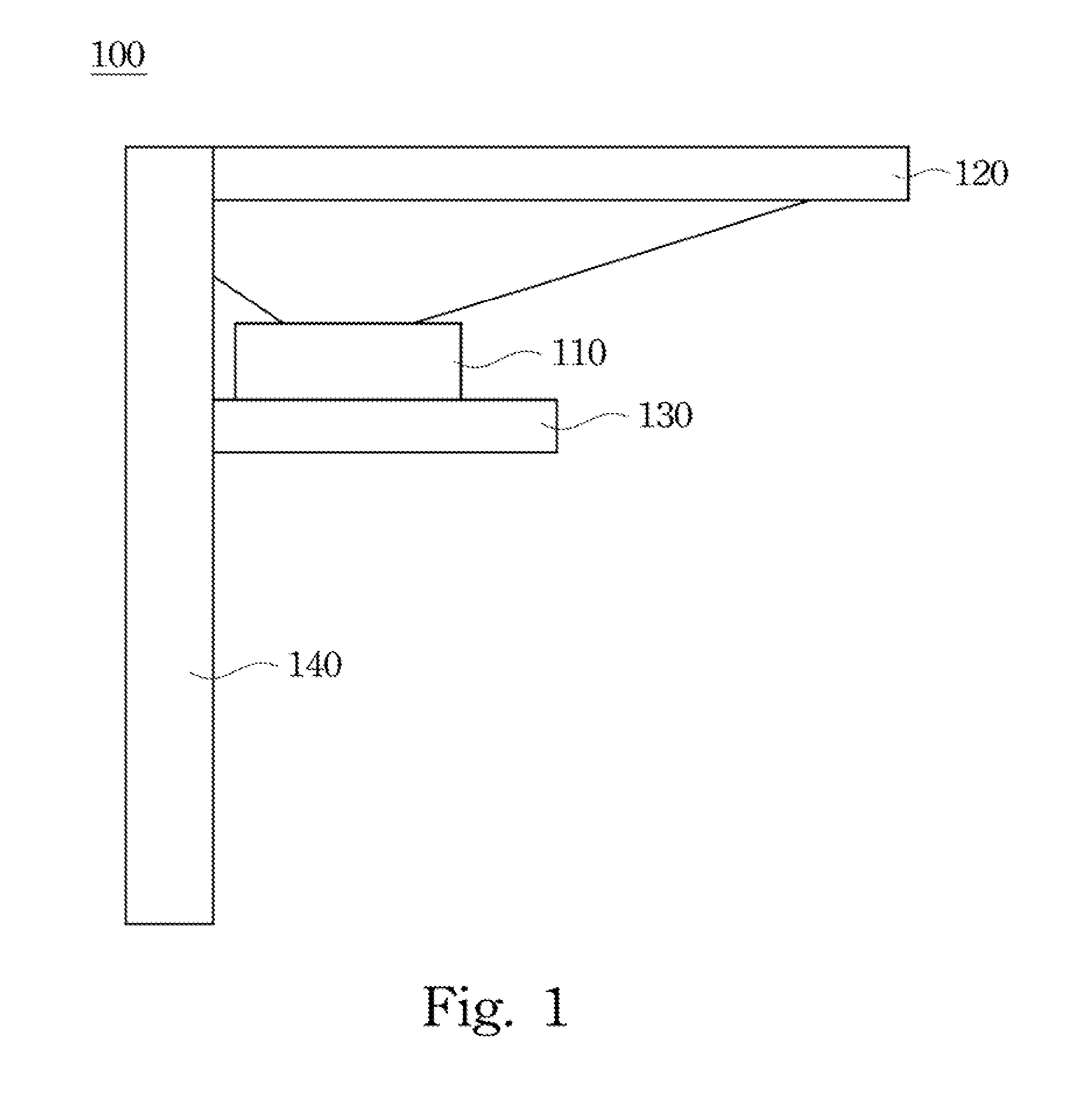
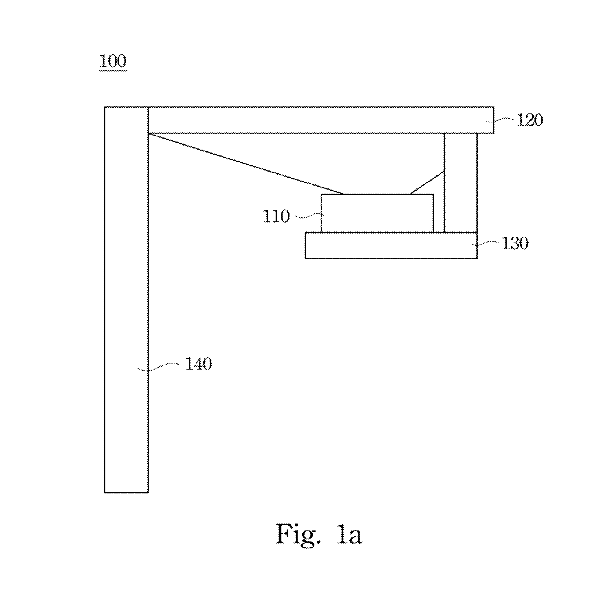
[0020]Referring to FIG. 1, FIG. 1 is a schematic diagram showing a structure of a cove lighting module 100 in accordance with an embodiment of the present invention. The cove lighting module 100 includes a lighting device 110, a light-receiving object 120, and a support member 130. The light-receiving object 120 has an opaque surface, or the material of the light-receiving object 120 is opaque material. In other words, the surface of the light-receiving object 120 is formed from fully reflective material or partially reflective material. The lighting device 110 is disposed on the support member 130, and project light onto the opaque surface of the light-receiving object 120, to provide illumination for indoor space of a building. In this embodiment, the light-receiving object 120 is a ceiling of the building, and the lighting device 110 is mounted on a sidewall 140 of the building through the support member 130, but the embodiments of the present invention are not limited thereto. I...


PUM


Abstract

A lighting device and a cove lighting module are provided. The lighting device includes a shell body, at least one light emitting diode element, and at least one light guide plate. The light emitting diode element and the light guide plate are disposed in the shell body. The light guide plate is disposed adjacent to the light emitting diode element to enable light emitted by the light emitting diode element to enter the light guide plate through a light incident surface of the light guide plate and to exit from the light guide plate through a light emitting surface of the light guide plate. The cove lighting module includes a light-receiving object and the lighting device, wherein the light-receiving object has an opaque surface. In the cove lighting module, the light exiting from the light guide plate is directly emitted to the opaque surface of the light-receiving object.

Description

CROSS REFERENCE TO RELATED APPLICATIONS[0001]This application is a Continuation-in-Part of U.S. application Ser. No. 13 / 528,863, filed on Jun. 21, 2012, which claims priority of Taiwan Patent Application No. 101113492, filed on Apr. 16, 2012, the entirety of which is incorporated by reference hereinBACKGROUND[0002]1. Field of Invention[0003]The present invention relates to a lighting device and a cove lighting module using the lighting device, and more particularly, to a lighting device using light emitting diodes (LEDs) as light sources and a cove lighting module using the lighting device.[0004]2. Description of Related Art[0005]In a common building, lamps are generally mounted on a ceiling to illuminate indoor space of the building. However, because direct lighting is very harsh to a user's eyes, the user's eyes may get tired easily. To overcome the disadvantage of the direct lighting, indirect lighting is presented to provide illumination for the building.[0006]The indirect light...

Claims


Application Information

Patent Timeline
Patent Type & Authority Applications(United States)
IPC IPC(8): F21V8/00
CPCG02B6/0055G02B6/0031G02B6/0011G02B6/0025G02B6/0035
Inventor WU, YI-TSUOTENG, YU-YUAN
Owner RADIANT OPTO ELECTRONICS
Why Eureka
Try Eureka