
Integration project center

a technology of integration project and project center, applied in the direction of program control, instrumentation, user interface execution, etc., can solve the problems of unintended consequences, not having the technical implementation details of functional decomposition, and not providing for operational management when put into production

Active Publication Date: 2014-08-07
ORACLE INT CORP
View PDF5 Cites 14 Cited by
  • Summary
  • Abstract
  • Description
  • Claims
  • Application Information

AI Technical Summary

Benefits of technology

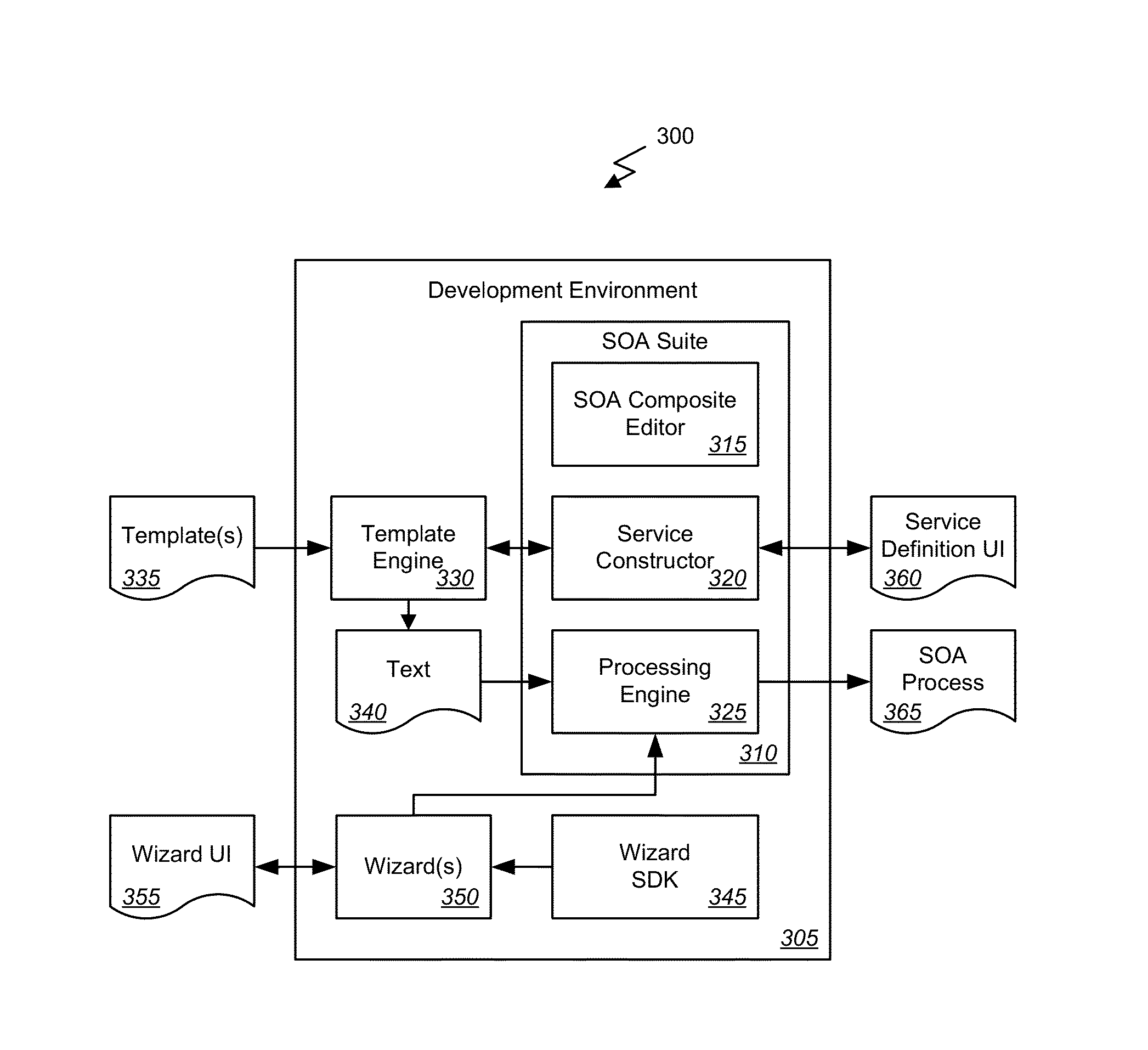
The invention provides a system and method to help define services in a SOA. It offers a way to create templates for different services, with code to define processes, tasks, or components. These templates can be associated with wizards that help fill in the necessary values for a particular service. At runtime, a selection of a template can be made, and if it's associated with a wizard, that wizard can be invoked to complete the service definition. This approach makes it easier for developers to create and test new services in a SOA environment.

Problems solved by technology

When constructing or implementing such services, SOA integration projects range from the very simple connection between two edge systems to large-scale business flows between many edge systems that result in collections of service artifacts.
This functional decomposition typically does not have the technical implementation details, but could be quite granular.
Technical debt is created by code that may solve an immediate requirement, but may do so with unintended implications, such as for example, failure to employ an error handling strategy.
While the code may do well in a unit test, it might not provide for operational management when put into production.
For example, following specific naming conventions, creating appropriate scopes, adding error-handling branches etc. are steps that may be documented but can be tedious for the developer to code for each scope.

Method used


Image

  • Integration project center
  • Integration project center
  • Integration project center

Examples


Embodiment Construction

[0014]In the following description, for the purposes of explanation, numerous specific details are set forth in order to provide a thorough understanding of various embodiments of the present invention. It will be apparent, however, to one skilled in the art that embodiments of the present invention may be practiced without some of these specific details. In other instances, well-known structures and devices are shown in block diagram form.

[0015]The ensuing description provides exemplary embodiments only, and is not intended to limit the scope, applicability, or configuration of the disclosure. Rather, the ensuing description of the exemplary embodiments will provide those skilled in the art with an enabling description for implementing an exemplary embodiment. It should be understood that various changes may be made in the function and arrangement of elements without departing from the spirit and scope of the invention as set forth in the appended claims.

[0016]Specific details are ...


PUM


Abstract

Embodiments of the present invention provide for supporting definition of services in the SOA using templates for definition of processes, tasks, and / or components and wizards associated to the templates for guiding users in defining values to variables in the templates. Embodiments of the present invention provide developers with a guided flow for an integration project as well as guidance from the functional decomposition from the solution architect within an integrated development environment. Embodiments provide pre-built templates that may also contain wizard based interfaces to help the developers to create services that follow best-practices and include necessary plumbing tasks. Embodiments described herein provide the ability to create and save BPEL projects and scopes as templates to be reused in later projects and the application of these template features with wizard interfaces and a project overview / checklist model to provide developer guidance and assistance in creating the service that follows best-practices.

Description

BACKGROUND OF THE INVENTION[0001]Embodiments of the present invention relate generally to methods and systems for supporting definition of services in a Service Oriented Architecture (SOA) and more particularly to supporting definition of services in the SOA using templates for definition of processes, tasks, and / or components and wizards associated to the templates for guiding users in defining values to variables in the templates.[0002]A Service Oriented Architecture (SOA) is a system, i.e., hardware, software, or a combination of hardware and software, providing services or business processes built upon sets of reusable components, e.g., software code, data structures, etc. When constructing or implementing such services, SOA integration projects range from the very simple connection between two edge systems to large-scale business flows between many edge systems that result in collections of service artifacts. To combat technical debt, organizations seek to build reusable compon...

Claims


Application Information

Patent Timeline
IPC IPC(8): G06F9/44
CPCG06F8/20G06F8/36G06F9/453
Inventor WUNDERLICH, JR., ROBERT DAVIDBUKHARI, MUNAZZABORTHAKUR, AVITHUKKARAM, PRABHUGEIB, SIMONEGANDHI, HARIMODI, RAJAN M.
Owner ORACLE INT CORP
Learn More