Brake System for Motor Vehicles and Method for Operating the Brake System

a technology for brake systems and motor vehicles, applied in braking systems, braking components, transportation and packaging, etc., can solve problems such as the inability to operate the brake system in the “brake-by-wire” operating mod

Inactive Publication Date: 2014-08-14
CONTINENTAL TEVES AG & CO OHG
View PDF5 Cites 49 Cited by
  • Summary
  • Abstract
  • Description
  • Claims
  • Application Information

AI Technical Summary

Problems solved by technology

It is felt that a serious disadvantage of the previously known brake system is the fact that in the event of a failure of the control or of th...

Method used


Image

  • Brake System for Motor Vehicles and Method for Operating the Brake System
  • Brake System for Motor Vehicles and Method for Operating the Brake System
  • Brake System for Motor Vehicles and Method for Operating the Brake System

Examples


Embodiment Construction

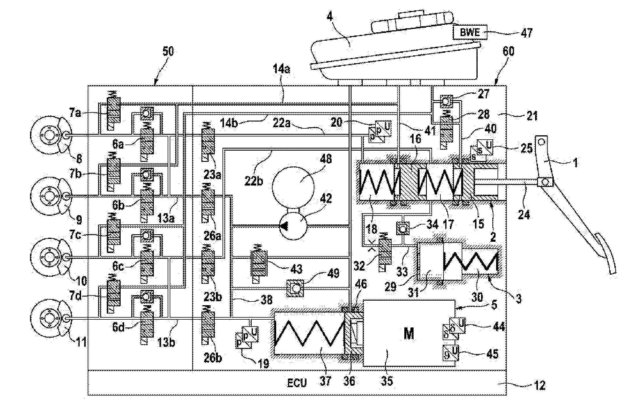
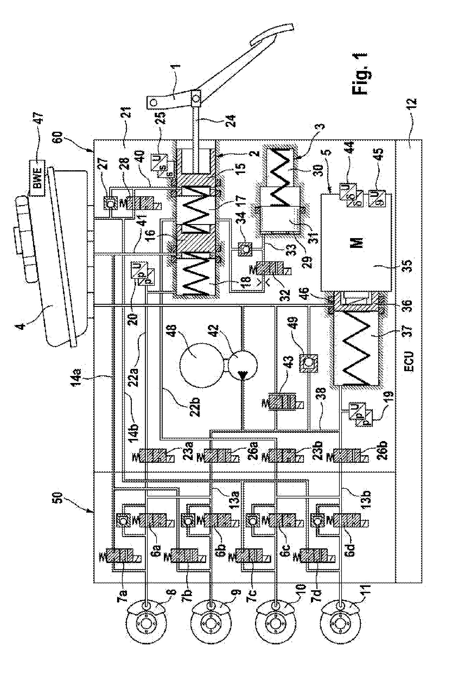
[0020]The brake system that is illustrated in the drawing comprises essentially a hydraulic actuation unit 2 that can be actuated by means of an actuation device and / or a brake pedal 1, a travel simulator 3 that works in conjunction with the hydraulic actuation unit 2, a pressure medium storage container 4 having an electric fill level sensor 47, which pressure medium storage container is allocated to the hydraulic actuation unit 2, a first electrically controllable pressure source 5, electrically controllable pressure modulation and / or intake and exhaust valves 6a-6d, 7a-7d, which are interconnected in pairs in a hydraulic manner by way of intermediate connectors and are connected to wheel brakes 8, 9, 10, 11 of a motor vehicle, not illustrated. The input connectors of the intake valves 6a-6d are supplied with pressures by means of brake circuit pressure lines 13a, 13b, which pressures in the “brake-by-wire” operating mode are provided by a (brake)system pressure, which is avai...


PUM


Abstract

A brake system includes a brake pedal for actuating a master cylinder having two pistons and corresponding pressure chambers, where the system can be operated in a brake-by-wire mode and also a fallback mode. The system also includes a first electrically controllable pressure source and a second electrically controllable pressure source. The first and second electrically controllable pressure sources each have corresponding output flows that are connected together. The second electrically controllable pressure source can therefore provide output volume flow in the event the first electrically controllable pressure source fails.

Description

CROSS-REFERENCE TO RELATED APPLICATIONS[0001]This application claims priority to German Patent Application Nos. 10 2011 017 703.5, filed Apr. 28, 2011 and 10 2012 202 645.2, filed Feb. 21, 2012, and PCT / EP2012 / 055942, filed Apr. 2, 2012.FIELD OF THE INVENTION[0002]The present invention relates to a brake system for motor vehicles, which can be controlled in a “brake-by-wire” operating mode both by the driver of the vehicle and also independently of the driver of the vehicle, which brake system is preferably operated in the “brake-by-wire” operating mode and can be operated in at least one fallback operating mode, in which only the operation by the driver of the vehicle is possible, having:[0003]a) a brake pedal for the purpose of actuating a master brake cylinder having a housing, two pistons that are arranged one behind the other, which pistons delimit two pressure chambers in the housing, upon which pistons an actuating force (pedal force) is exerted during actuation of the brake ...

Claims


Application Information

Patent Timeline
IPC IPC(8): B60T13/66B60T13/58
CPCB60T13/58B60T13/662B60T7/042B60T8/321B60T8/4081B60T8/885B60T13/146B60T13/686B60T2270/402B60T2270/404B60T2270/82B60T13/745
Inventor DRUMM, STEFAN A.LINKENBACH, STEFFEN
Owner CONTINENTAL TEVES AG & CO OHG
Why Eureka
Try Eureka