Battery monitoring network

a battery monitoring and network technology, applied in the field of battery monitoring, can solve the problems of terminal failure, physical connection to the terminal requires special equipment, and current battery efficiency or even failure,

Active Publication Date: 2014-08-14
CPS TECH HLDG LLC
View PDF26 Cites 88 Cited by
  • Summary
  • Abstract
  • Description
  • Claims
  • Application Information

AI Technical Summary

Benefits of technology

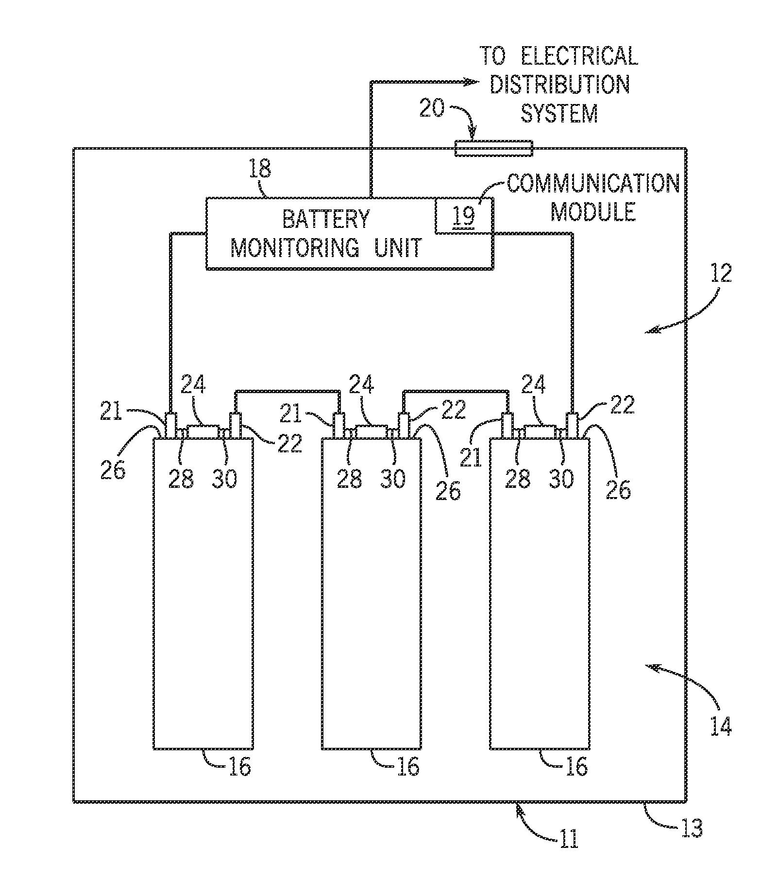
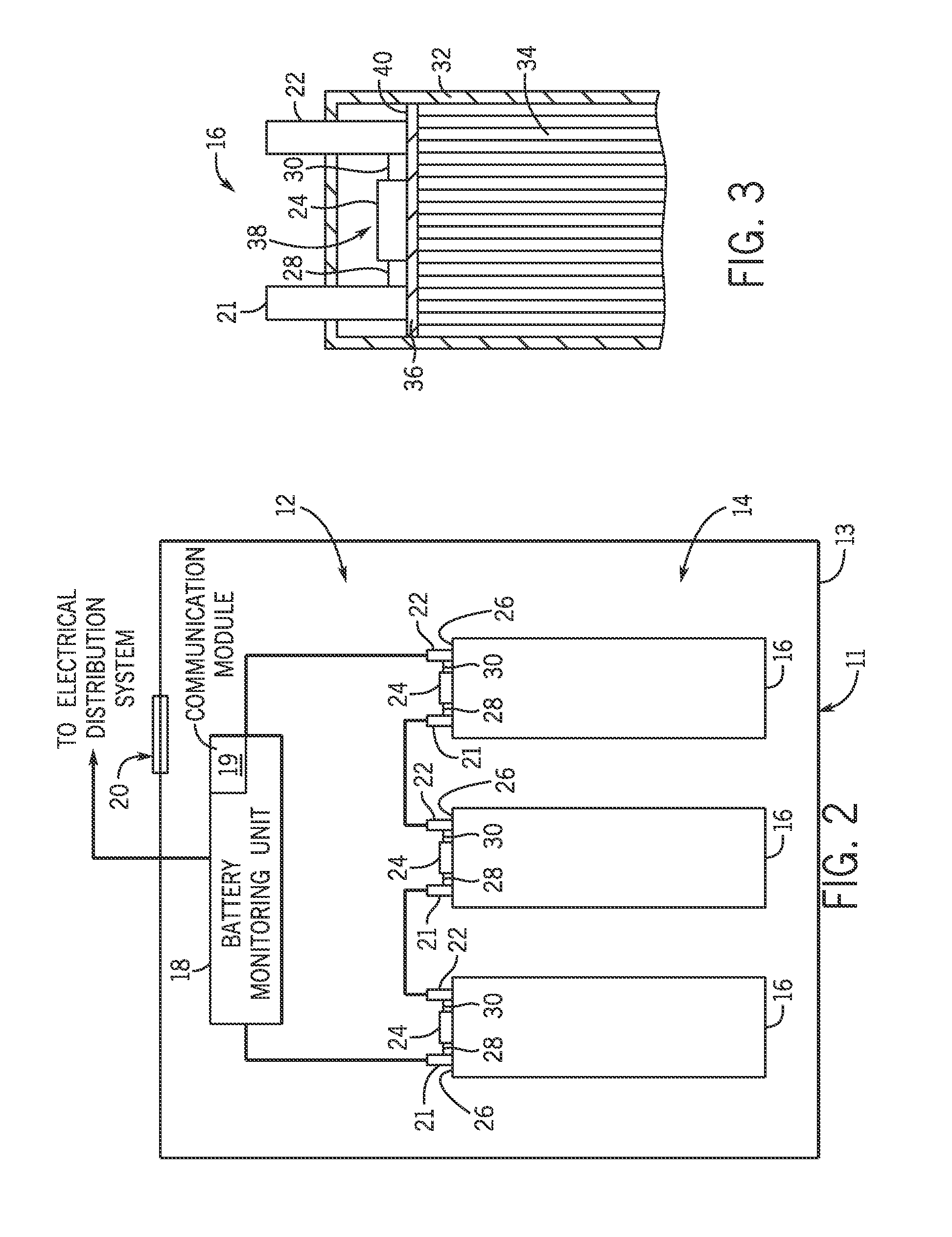
[0004]In one embodiment, a battery monitoring network includes a battery. The battery monitoring network also includes a battery monitoring system integrated within the battery. The battery monitoring system includes a diagnostic system configured to monitor or to store one or more battery parameters of the battery. Additionally, the battery monitoring system includes a transmitter configured to transmit data indicative of the one or more battery parameters of the battery. Furthermore, battery monitoring network includes a cloud-based computing network having a remote server configured to receive the data indicative of the one or more battery parameters of the battery. Moreover, the cloud-based computing network is configured to interface with a plurality of battery monitoring systems, and includes an internet connection.
[0005]In another embodiment, a method for monitoring a battery includes monitoring or storing one or more battery parameters of the battery via a battery monitoring system integrated within the battery. The method also includes transmitting data indicative of the one or more battery parameters of the battery to a cloud-based computing network. Moreover, the cloud-based computing network is configured to interface with a plurality of battery monitoring systems, and comprises an internet connection.

Problems solved by technology

However, current batteries lose efficiency or even fail after various periods or conditions of use.
However, these battery testers usually convey charge information through physical connections to terminals of the battery, but testing using a physical connection to the terminals requires special equipment that may not be available or requires visiting a maintenance location.
Additionally, these terminals may become corroded or warped due to the environment in which the battery is operated (e.g., engine compartment) causing the terminals to fail when the connections to the terminals are removed or moved to connect a battery tester.

Method used


Image

  • Battery monitoring network
  • Battery monitoring network
  • Battery monitoring network

Examples


Embodiment Construction

[0015]One or more specific embodiments of the present invention will be described below. In an effort to provide a concise description of these embodiments, all features of an actual implementation may not be described in the specification. It should be appreciated that in the development of any such actual implementation, as in any engineering or design project, numerous implementation-specific decisions must be made to achieve the developers' specific goals, such as compliance with system-related and business-related constraints, which may vary from one implementation to another. Moreover, it should be appreciated that such a development effort might be complex and time consuming, but would nevertheless be a routine undertaking of design, fabrication, and manufacture for those of ordinary skill having the benefit of this disclosure.

[0016]When introducing elements of various embodiments of the present invention, the articles “a,”“an,”“the,” and “said” are intended to mean that ther...


PUM


Abstract

A battery monitoring network is provided that includes a battery. The battery monitoring network also includes a battery monitoring system integrated within the battery. The battery monitoring system includes a diagnostic system configured to monitor or to store one or more battery parameters of the battery. Additionally, the battery monitoring system includes a transmitter configured to transmit data indicative of the one or more battery parameters of the battery. Furthermore, battery monitoring network includes a cloud-based computing network having a remote server configured to receive the data indicative of the one or more battery parameters of the battery. Moreover, the cloud-based computing network is configured to interface with a plurality of battery monitoring systems, and includes an internet connection.

Description

CROSS REFERENCE TO RELATED APPLICATION[0001]This application claims priority from and the benefit of U.S. Provisional Application Ser. No. 61 / 763,814, entitled “BATTERY MONITORING NETWORK”, filed Feb. 12, 2013, which is hereby incorporated by reference in its entirety.BACKGROUND[0002]The present disclosure relates generally to battery monitoring. More particularly, the disclosure relates to techniques for monitoring battery characteristics using cloud computing.[0003]Certain devices (e.g., vehicles) incorporate batteries to enable device activation or operation of various electrical systems or motors within the device. However, current batteries lose efficiency or even fail after various periods or conditions of use. It is desirable to determine the state of the battery before the battery fails. Certain battery testers enable a user to determine whether the battery has a charge or is operable. However, these battery testers usually convey charge information through physical connecti...

Claims


Application Information

Patent Timeline
Patent Type & Authority Applications(United States)
IPC IPC(8): G01R31/36
CPCG01R31/3606B60L2240/545B60L2240/547B60L2240/549B60L2240/70B60L2240/80B60L2260/44B60L50/15B60L58/16H01M2010/4278H04B3/548H04B2203/5445H04B2203/5458H04Q9/00H04Q2209/10H04Q2209/40H04Q2209/43H04Q2209/883Y02E60/10Y02T10/70Y02T10/7072Y02T10/72Y02T90/16G01R31/382
Inventor CAMPBELL, DOUGLAS C.SIMS, MICHAEL J.EICH, RODGER W.MORELL, THOMAS H.GOSPODARAK, DALE A.SYMANSKI, JAMES S.
Owner CPS TECH HLDG LLC
Why Eureka
Try Eureka