Surgical guide for implanting a knee prosthesis

a surgical guide and knee technology, applied in the field of surgical guide for implanting a knee prosthesis, can solve the problems of insufficient bone visibility, interference of the cutting device with the rotula tendon, and inability to be free from drawbacks, and achieve the effect of high stability

Active Publication Date: 2014-08-21
MEDACTA INT SA
View PDF9 Cites 11 Cited by
  • Summary
  • Abstract
  • Description
  • Claims
  • Application Information

AI Technical Summary

Benefits of technology

[0028]A crucial aspect of the invention is that the femoral guide, designed based on the same anatomy of the single patient, gives such accuracy to the device as to ensure a unique positioning and a high stability.
[0029]According to a further aspect of the finding, the guide for the outer rotation can rotate op

Problems solved by technology

In conclusion, these and other patents (more or less recent) and the relevant devices used to date certainly have important merits but unfortunately they are not free from drawbacks, such as those that relate to an insufficient mini-invasiveness, the interference of the cutting device with the rotula tendon and an insufficient visibility of the bone.
On the other hand, however, patient specific guides have a drawback due to the strictness of the preoperative planning.
In fact, while CAT images allow seeing the bony markers generally s

Method used


Image

  • Surgical guide for implanting a knee prosthesis
  • Surgical guide for implanting a knee prosthesis
  • Surgical guide for implanting a knee prosthesis

Examples


first embodiment

[0062]The structure of the first component G1′, however, is slightly modified compared to the first embodiment version.

[0063]In particular, the arch structure Ar whereon template Gr is hinged is here replaced by a attachment plate Pi. It should be noted that the attachment plate Pi has smaller dimensions than the arch structure Ar proposed in the previous version. The modification made advantageously allows the patient's leg to be extended during the operation; in the first embodiment version, the dimensions in side direction of the arch structure Ar prevent such operation.

[0064]The attachment plate Pi is connected by means of a connection Sff to a main attachment portion Gd. Connection Sff and attachment portion Gd are totally similar to those described above, except for the fact that the attachment portion Gd comprises a seventh fixing hole 25, skewed with respect to the six ones already provided in the first embodiment version.

second embodiment

[0065]On the contrary, the second embodiment version is not provided with the secondary attachment portions Ga, since it is provided with two distal fixing holes DFH directly onto the attachment plate Pi, which among the other things is designed for resting against the bony site defining the unique coupling of the first component G1′.

[0066]The attachment plate Pi, visible in FIG. 8 without the other elements associated thereto, has a substantially triangular shape. Distal fixing holes DFH are provided at the vertices of the base of such triangle; two coupling holes HTS for a shim are made a little above. In a central position at the height of the coupling holes HTS, substantially aligned with the longitudinal axis of femur Fe, there is provided a circular seat JRA wherein a button (not visible in the figures) of template Gr′ rotatably couples. Template Gr′ therefore is partly overlapped on plate Pi and rotatably constrained thereto.

[0067]Template Gr′ has a polygonal geometry, in par...


PUM


Abstract

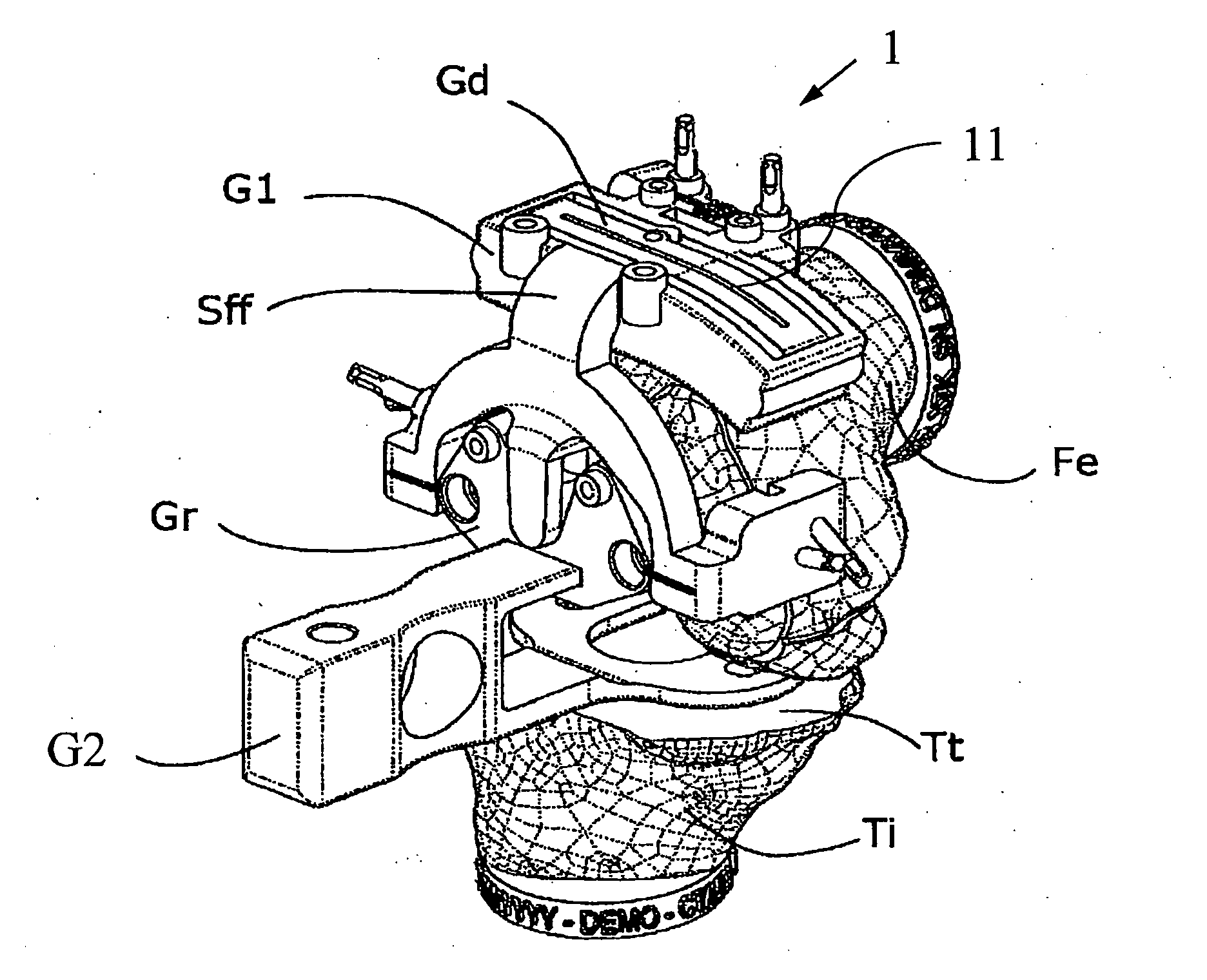
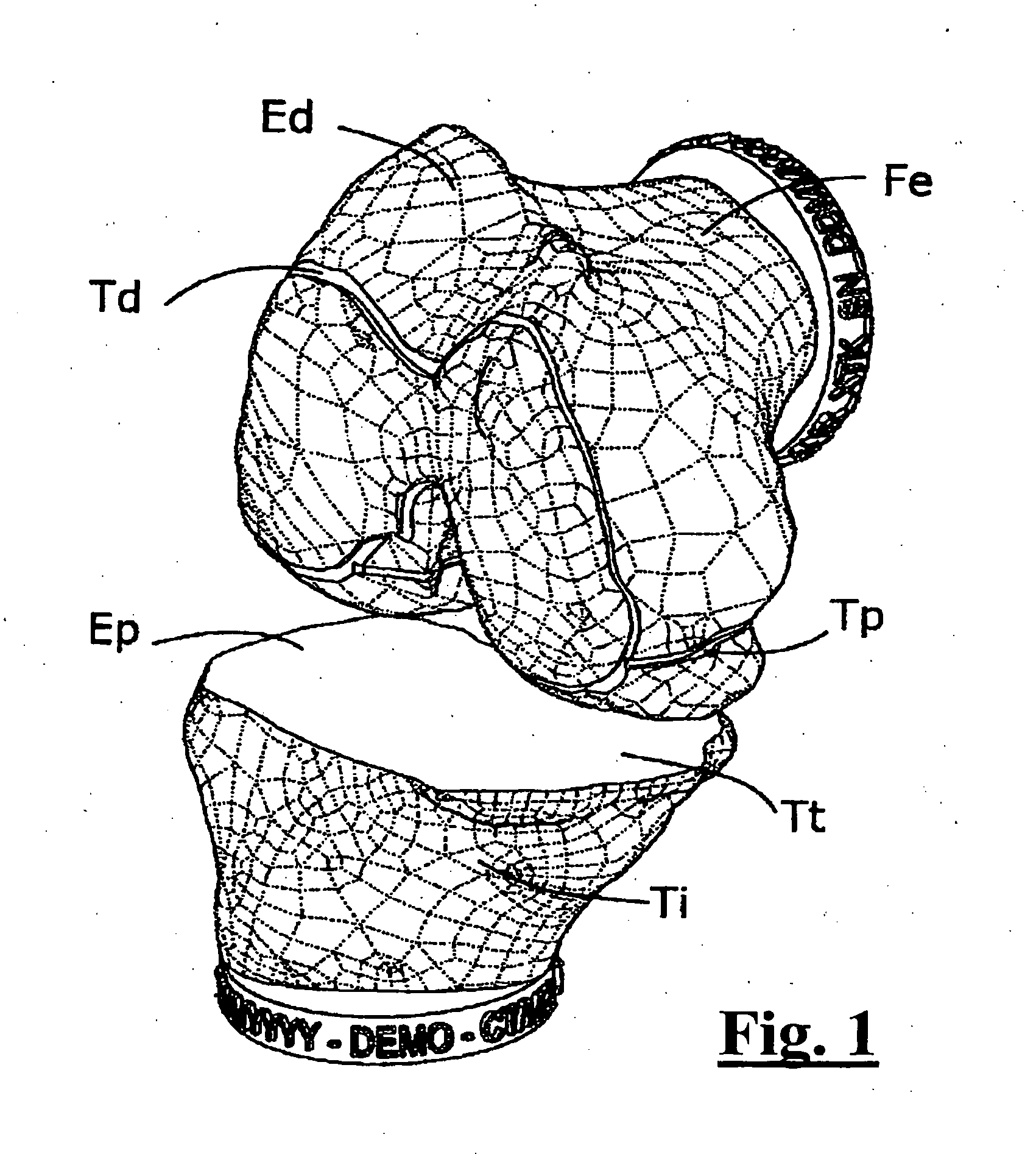
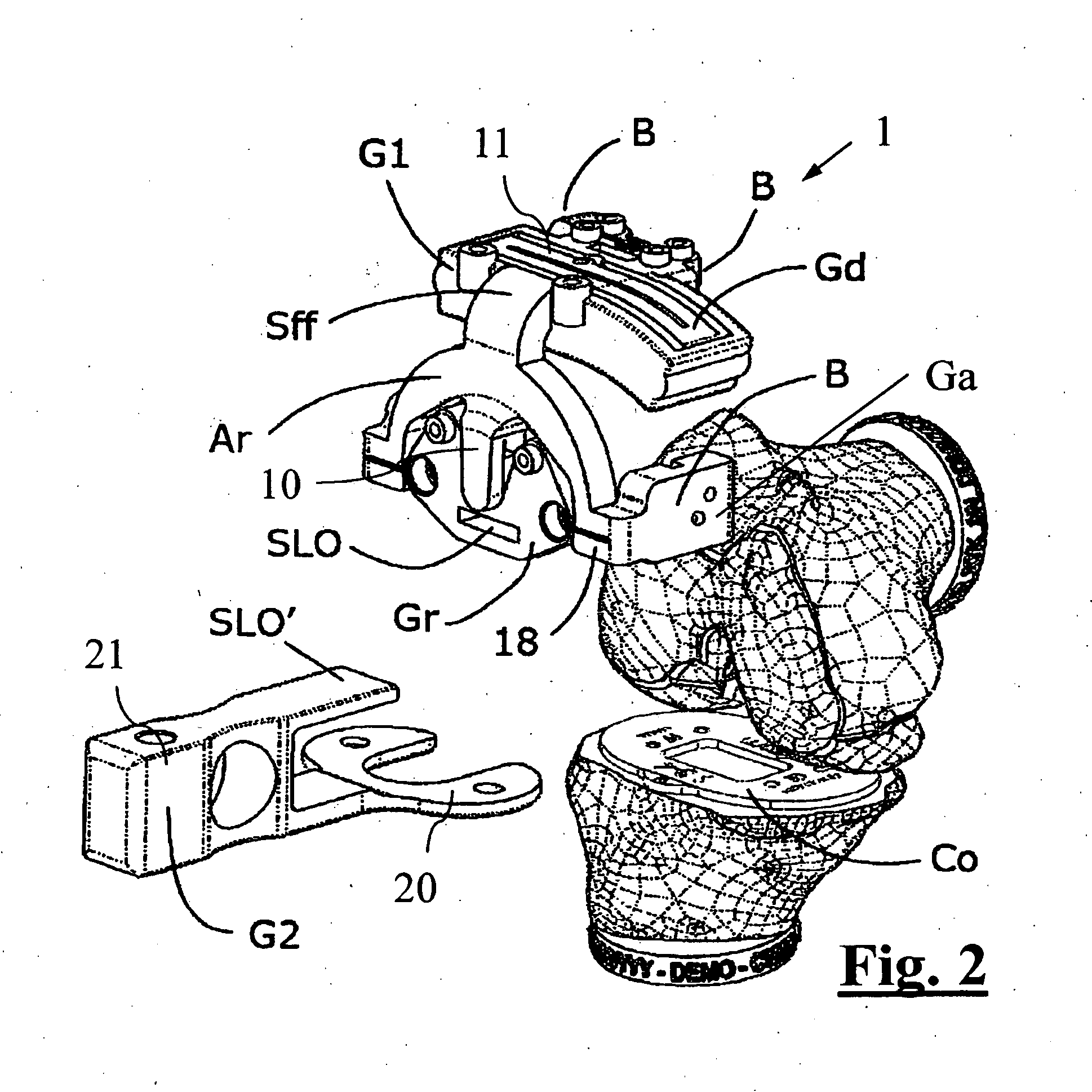
The invention relates to a surgical guide (1, 1′) for implanting a knee prosthesis, advantageously capable of allowing the intraoperative balancing of the knee ligaments, comprising: a first component (G1, G1′) intended for uniquely coupling with the distal epiphyseal end (Ed) of a femur (Fe); a template (Gr, Gr′) rotatably mounted with respect to said first component (G1, G1′) and intended for guiding a marking operation of said distal epiphyseal end (Ed) aimed to determine the position of a knee prosthesis to be implanted; and a second component (G2) intended for solidly coupling said template (Gr, Gr′) with a proximal epiphyseal end (Ep) of a tibia (Ti) corresponding to said femur (Fe).

Description

FIELD OF APPLICATION[0001]The present invention relates to a surgical guide for implanting a knee prosthesis, and in particular to a guide designed for the intraoperative alignment and balancing of the knee ligaments, of the type comprising a first component that uniquely couples with the distal femoral epiphyseal end, and a second component for coupling with the proximal tibial epiphyseal end.[0002]More in particular, the surgical guide used herein for balancing the knee ligaments is associated with an upper femoral end, and with a lower tibial end, preferably with a cover (although partial); it comprises intermediate coupling means of said ends and further means for guiding a distal cut.[0003]In one embodiment of the invention, the surgical guide is of the type that uses, among the others, a device having a frame comprising at least two adjustment means, in particular a sliding guide for defining the cutting height, and a guide, namely a turning guide, for defining the outer rotat...

Claims


Application Information

Patent Timeline
IPC IPC(8): A61F2/46A61F2/38
CPCA61F2/38A61F2/461A61B17/155A61B17/1764A61B2017/568
Inventor OLGIATI, GIANLUCABERNARDONI, MASSIMILIANOSICCARDI, FRANCESCOSICCARDI, ALBERTO
Owner MEDACTA INT SA
Why Eureka
Try Eureka