

GUI implementations on central controller computer system for supporting protocol independent device testing
a technology of a central controller and a computer system, applied in the direction of error detection/correction, instruments, computing, etc., can solve the problems of consuming critical time for replacing hardware bus adapter cards and reconfiguring hardware, and system can only test duts, etc., to achieve the effect of rapid configuration of complex programmable tester modules
Inactive Publication Date: 2014-08-21
ADVANTEST CORP
View PDF21 Cites 84 Cited by
- Summary
- Abstract
- Description
- Claims
- Application Information
AI Technical Summary
Benefits of technology
[0018]Disclosed herein is a method for configuring a programmable tester module, wherein the tester module comprises a reconfigurable circuit for implementing one of a plurality
Problems solved by technology
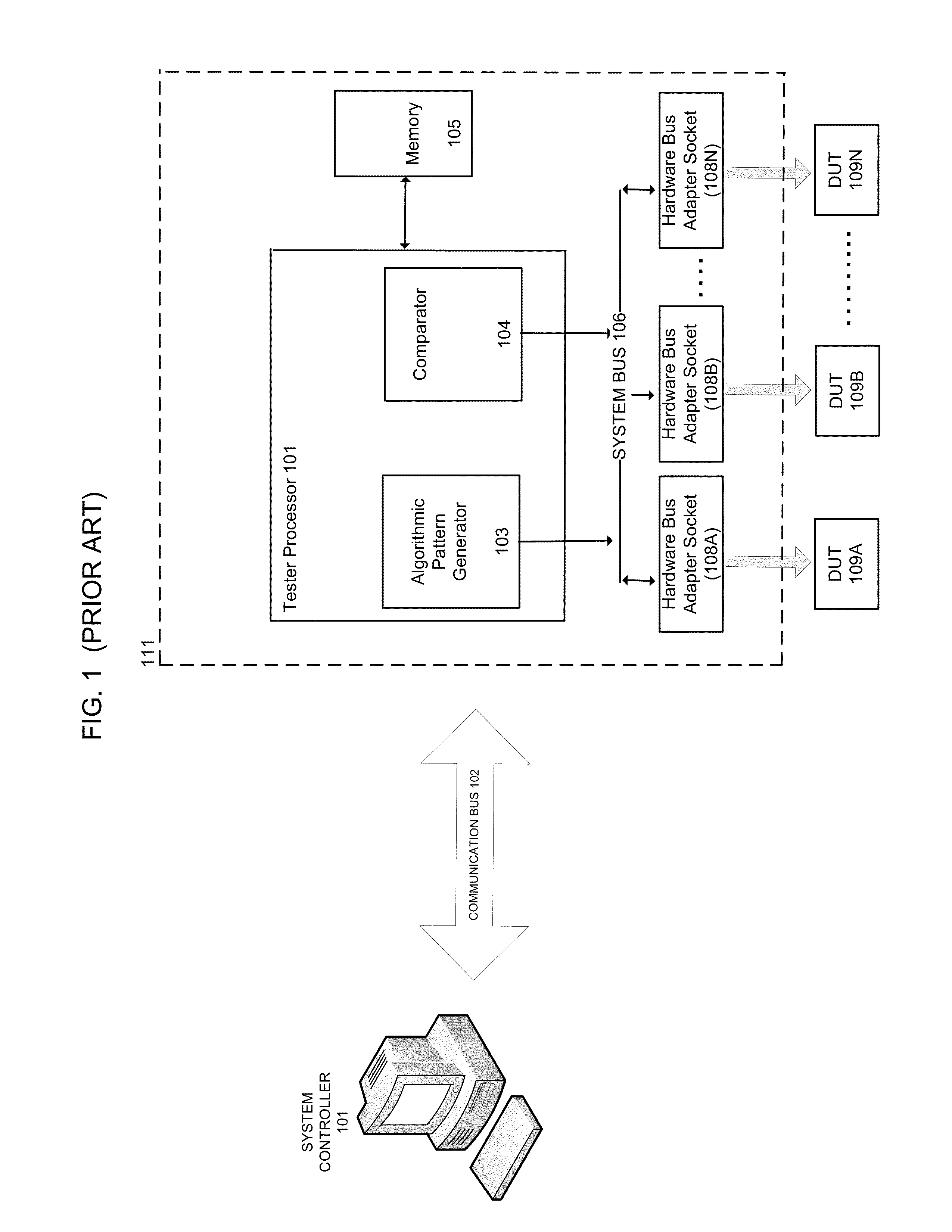
Typically, the end result of a test is either “pass” if the device successfully provides certain expected responses within pre-established tolerances, or “fail” if the device does not provide the expected responses within the pre-established tolerances.
Unless the PCIe hardware bus adapter cards are physically substituted with cards supporting the other protocol, such a system can only
Method used
View moreImage
Smart ImageViewing Examples

Examples
 PUM
 Abstract
A method for performing tests using automated test equipment (ATE) is presented. The method comprises obtaining a protocol selection for programming a programmable tester module using a graphical user interface (GUI). Further, the method comprises configuring the programmable tester module with a communication protocol for application to at least one device under test (DUT), wherein the at least one DUT is communicatively coupled to the programmable tester module. Also the method comprises providing a menu of tests associated with the communication protocol using the GUI and obtaining a program flow using the GUI, wherein the program flow comprises a sequence of tests chosen from the menu of tests. Finally, the method comprises transmitting instructions to the programmable tester module for executing the program flow.
Description
CROSS-REFERENCE TO RELATED APPLICATIONSRelated Applications[0001]The present application is related to U.S. patent application Ser. No. ______, filed ______, entitled “TESTER WITH MIXED PROTOCOL ENGINE IN FPGA BLOCK,” naming John Frediani and Andrew Niemic as inventors, and having attorney docket number ATST-JP0089. That application is incorporated herein by reference in its entirety and for all purposes.[0002]The present application is related to U.S. patent application Ser. No. ______, filed ______, entitled “A TESTER WITH ACCELERATION ON MEMORY AND ACCELERATION FOR AUTOMATIC PATTERN GENERATION WITHIN A FPGA BLOCK,” naming John Frediani as inventor, and having attorney docket number ATST-JP0091. That application is incorporated herein by reference in its entirety and for all purposes.[0003]The present application is related to U.S. patent application Ser. No. ______, filed ______, entitled “A TEST ARCHITECTURE HAVING MULTIPLE FPGA BASED HARDWARE ACCELERATOR BLOCKS FOR TESTING MULT...
Claims
Login to View More Application Information
Patent Timeline
 IPC IPC(8): G06F11/273
CPCG06F11/2733
InventorCHAN, GERALD
OwnerADVANTEST CORP