[0039]Another advantage of the present invention is a manufacturing process and construction methodology resultant in a product that is a load baring first course called a leveling base panel. Every system requires the site construction to begin on the slab and / or foundation. The leveling base panel allows immediate installation of subsequent construction upon it. The present invention allows for a single base course to be installed in minutes instead of hours painstaking leveling. Another advantage is that the subsequent construction is able to commence immediately instead of waiting hours so the first course can cure before putting weight on it. The house is designed in modular 2′ grid system so the leveling base panel can be cut in the factory, but also cut in the field for onsite modifications. The leveling base panel is architecturally finished and has an interior liquid sheetrock finish applied thereby eliminating several time consuming and costly steps in construction process. The architectural features are functional in that the architectural features are located at the top where there will be the mortar joint for subsequent course of wall block, as taught by the invention. Therefore the ⅛″ seam becomes invisible, again saving time and labor in finishing.
[0040]Because the leveling base panel teaches a utility chase incorporated therein, there is no need for further labor. Therefore, the advantages of the present invention are a leveling, structural and immediately load bearing, primary course of leveling base panels that incorporate architectural features which eliminate the need for further finishing and also incorporate a continuous utility chase system so the trades simply install their mechanical wires, piping, etc., requiring no further modifications. The invention's process of cutting out door openings and 45° corners into the leveling base panel after installation allows for greater accuracy, quicker installation, a consistent and precise leveling. Therefore, minimal waste pieces of cut out sections are easily and environmentally transformed to benefit the ecology.
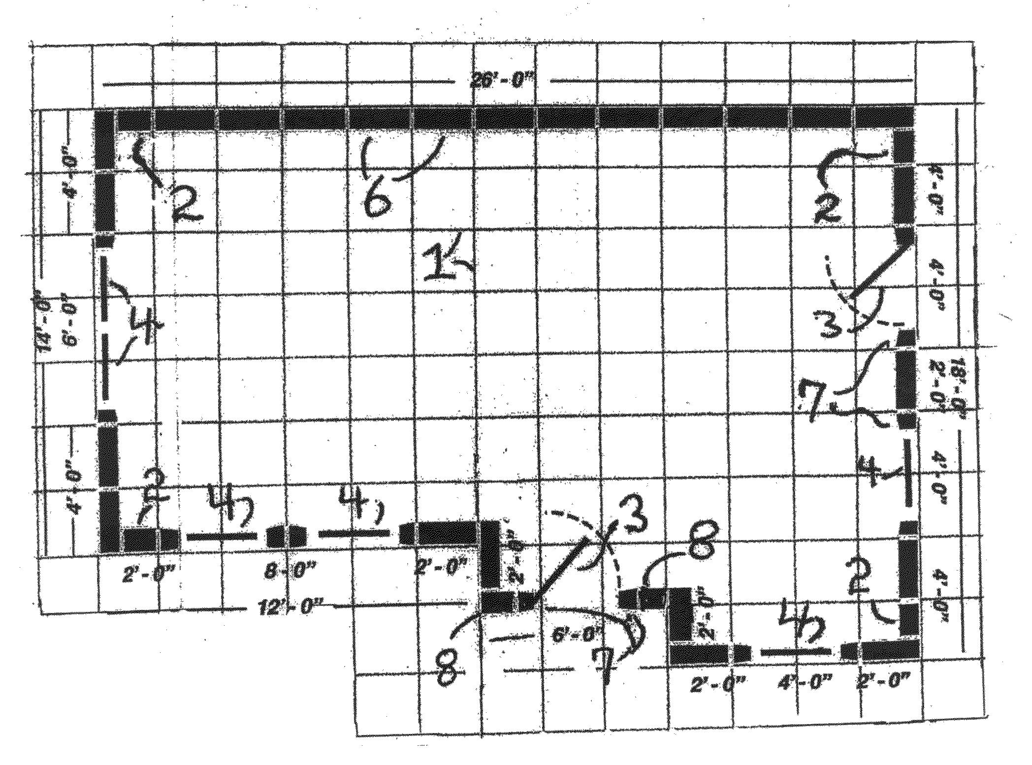
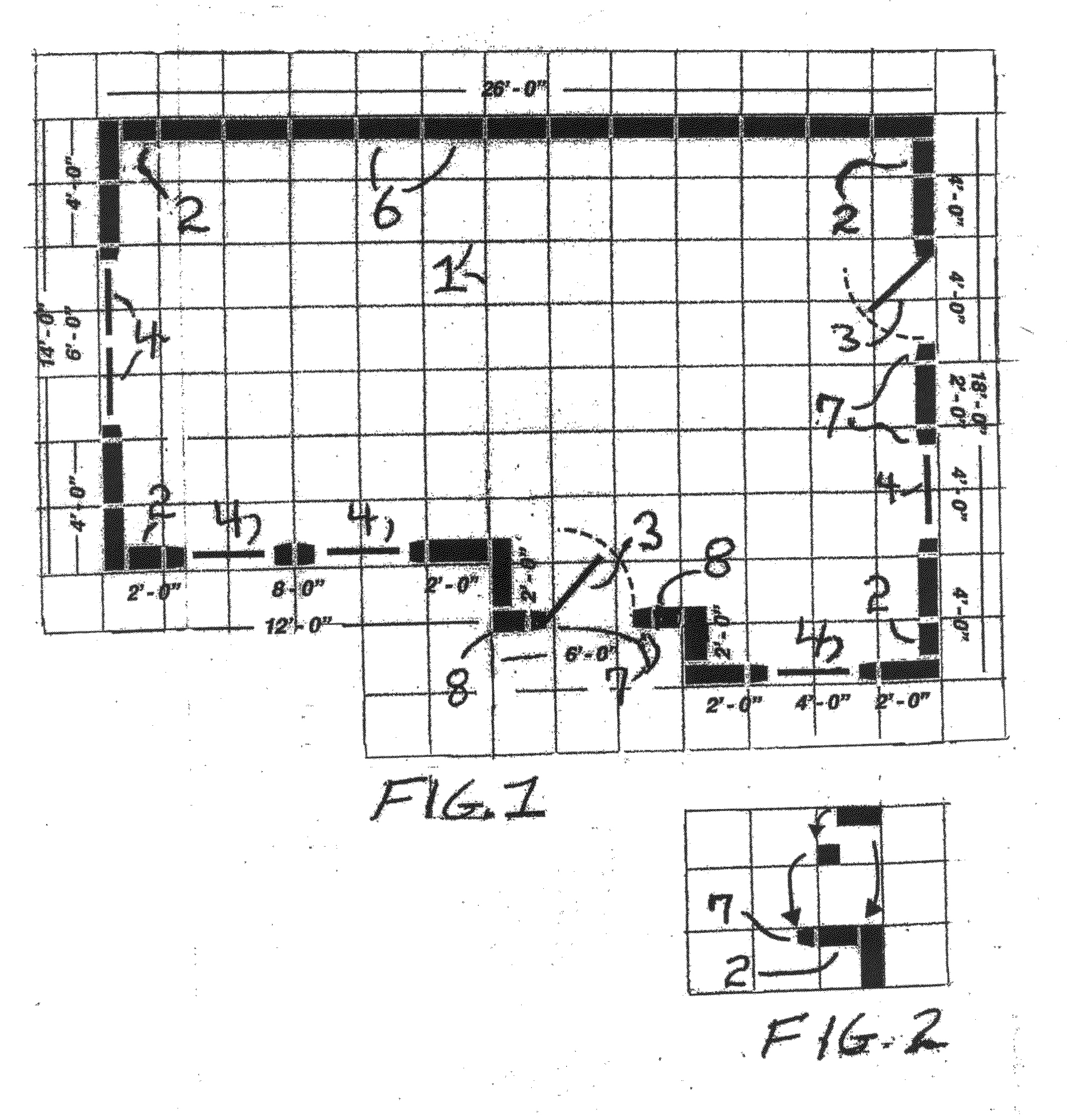
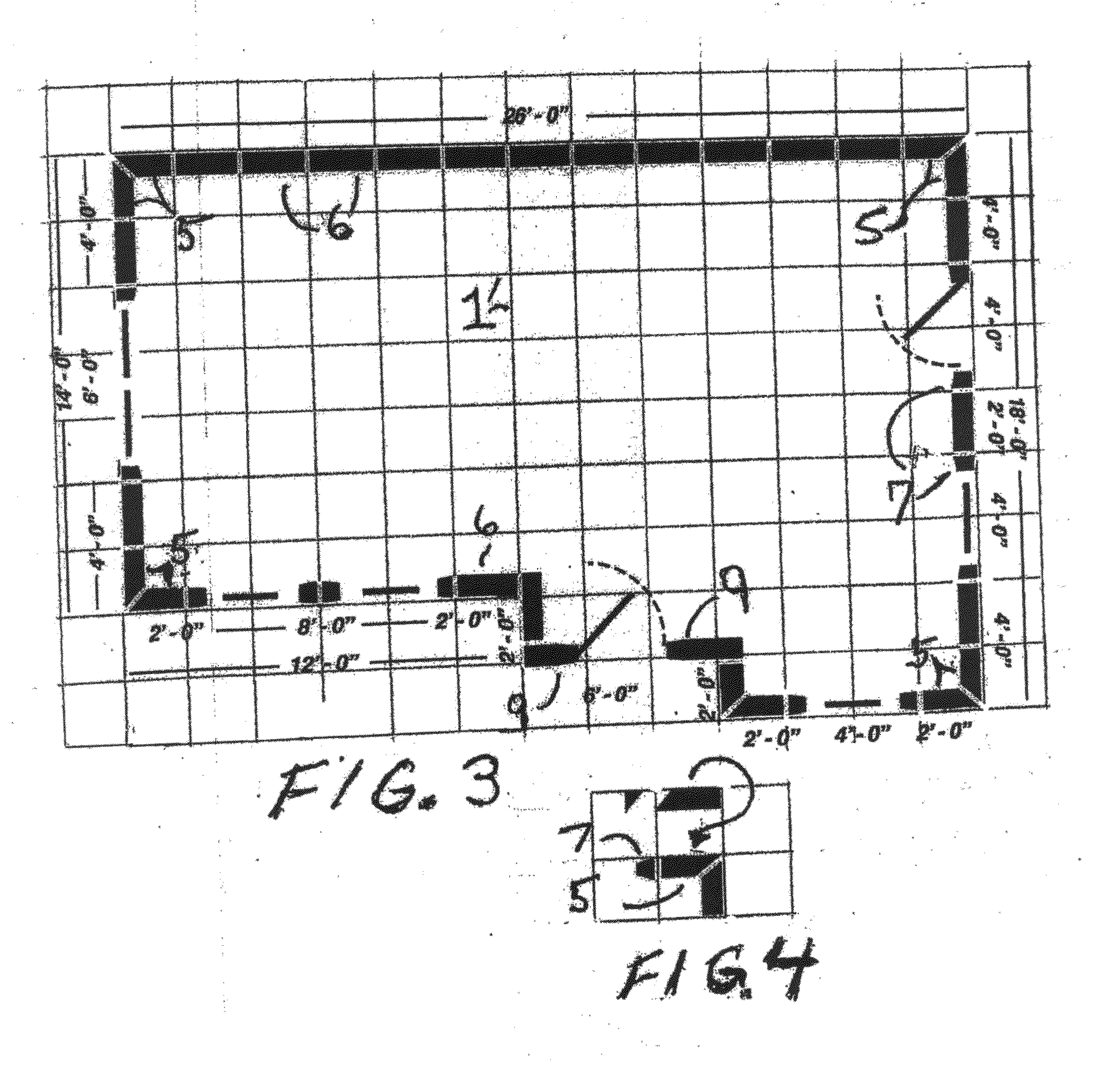
[0041]Another object of this invention is the filler wall block that is coordinated with the computerized grid system design, in this case employing the preferred 2′ grid, and how the dimensional non-architecturally finished wall block and casing blocks allow for aesthetically pleasing design variations without cutting or waste. At the end of the wall section that terminates at a perpendicular wall there is installed a filler wall block instead of a standard wall block. The filler wall block is a factory modified wall block that has its width reduced by the thickness of the wall it abuts so the 2′ grid is maintained. By employing only these two vertical block types, wall and filler, an entire habitat with a myriad of possible variations can be easily built and coordinated with the zero waste precast cementious roof system so the entire habitat has no waste in its vertical wall sections.
[0042]Another object of this invention is the filler wall block that is coordinated with the computerized grid system design, in this case employing the preferred 2′ grid, and how the dimensional non-architecturally finished wall block and casing blocks allow for aesthetically pleasing design variations without cutting or waste. At the end of wall section that terminates at a perpendicular wall there is installed a filler wall block instead of a standard wall block. The filler wall block is a wall block that has its width reduced by the thickness of the wall it abuts so the 2′ grid is maintained. By employing the primary three vertical block types (leveling base panel, wall block and top beam), the teachings of this invention of casing and space components enable an entire habitat to be easily built and coordinated with the zero waste precast cementious roof system so the entire habitat has almost no waste. The trimmings of the wall block are put through the invention's planer / molder machine and become window and door casing that is fireproof, termite proof, mold proof, nondecaying and insulating.
[0043]Another alternative object of this invention is for when employing wall blocks that have manufactured architecturally finish on the exterior surface to make a continuous pattern on exterior of house requires 45° cuts on the vertical sides at outside corners so that the grid system, in this case on typical 2′ grid, allows for good architectural design variation. For inside corners the teaching of this invention corner block is employed. Thereby employing only these three vertical block types, wall, casing and corner, an entire habitat is easily built and coordinated with a precast cementious roof system that has zero waste.
[0044]Another object of this invention is when the architecturally finished wall blocks use a simulated siding design, it is necessary to replace vertically orientated wall blocks with this invention's horizontal wall blocks. Horizontal wall blocks are approximately 10′ long and have minimal reinforcing for transporting and erecting because their primary function requires compressive strength, not sheer strength. Since the horizontal blocks are employed within the present invention's “CGS” (computerized grid system), there is rarely waste as the 2′ incremental sections are easily installed at various places.

