

Imaging lens and imaging apparatus
a technology of imaging apparatus and lens, applied in the field of imaging lenses, can solve the problems of difficult correction of aberrations, insufficient wide angle of view, and extremely difficult to obtain favorable image quality through peripheral parts, and achieve the suppression of comatic aberrations, telecentric properties lost, and comatic
- Summary
- Abstract
- Description
- Claims
- Application Information
AI Technical Summary
Benefits of technology
Problems solved by technology
Method used
Image

Examples
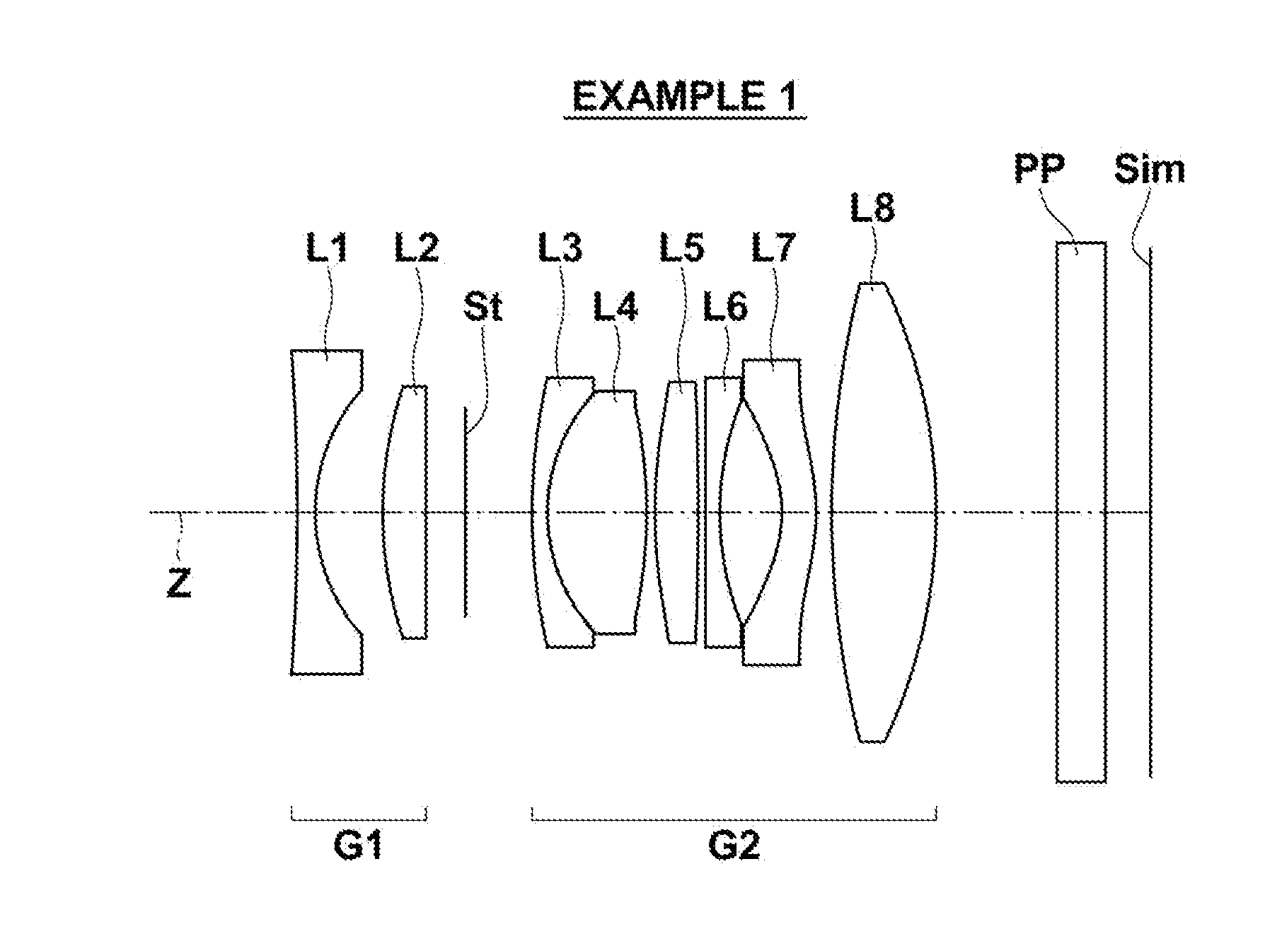
example 1
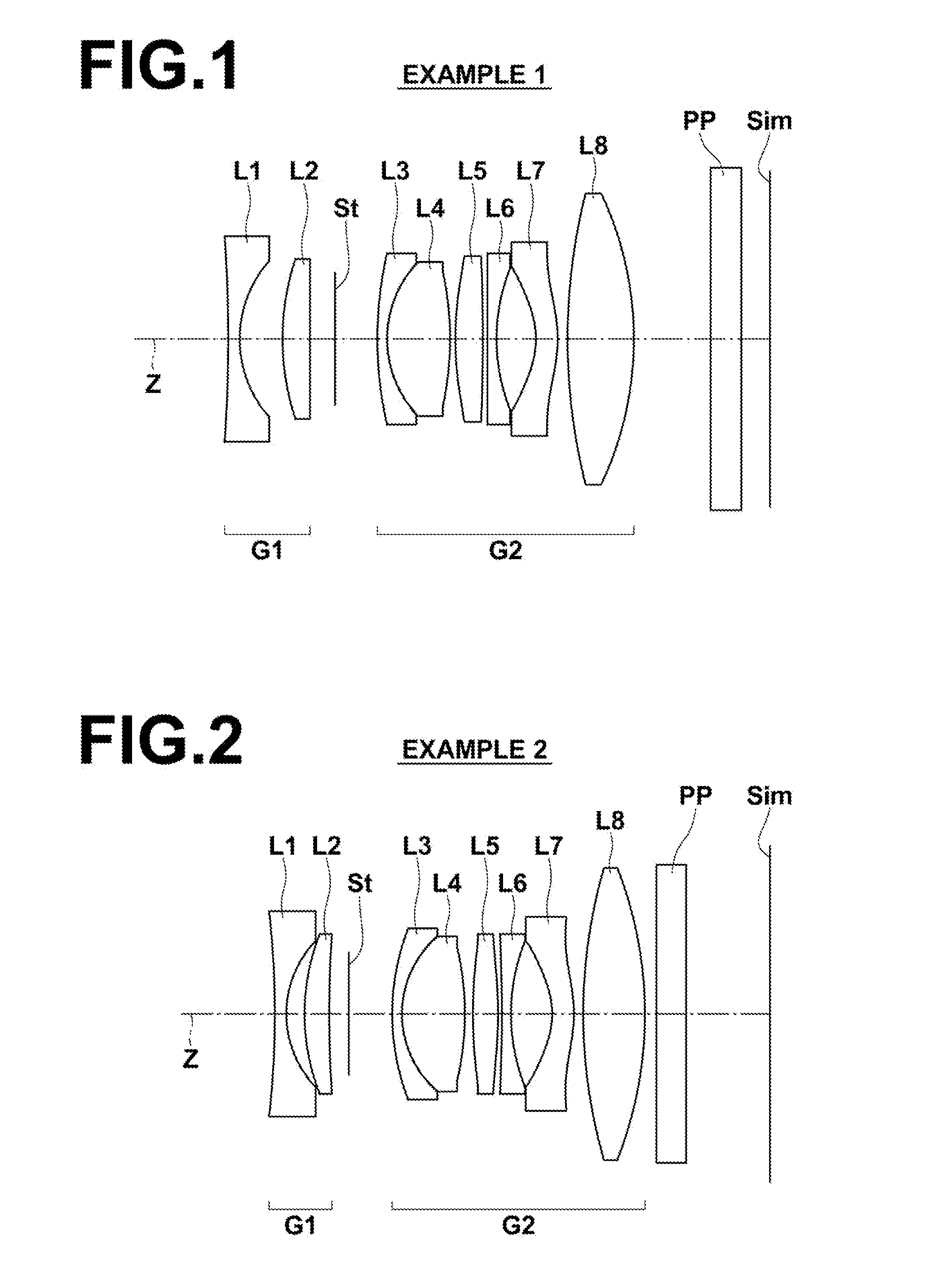
[0127]As described previously, the arrangement of the lens groups within the imaging lens of Example 1 is illustrated in FIG. 1. Note that the details of the lens groups and each lens in the configuration of FIG. 1 have been described previously. Therefore, redundant descriptions will be omitted below, unless particularly necessary.
[0128]Table 1 shows basic lens data of the imaging lens of Example 1. Table 1 also shows data regarding the optical member PP. In Table 1, ith (i=1, 2, 3, . . . ) lens surface numbers that sequentially increase from the object side to the image side, with the lens surface at the most object side designated as first, are shown in the column Si. The radii of curvature of ith surfaces are shown in the column Ri, and the distances between an ith surface and an i+1st surface along the optical axis Z are shown in the column Di. The refractive indices of jth (j=1, 2, 3, . . . ) optical elements from the object side to the image side with respect to the d line (w...
example 2
[0138]FIG. 2 illustrates the arrangement of lens groups in the imaging lens of Example 2. The imaging lens of Example 2 is of approximately the same configuration as the imaging lens of Example 1 described above. However, the imaging lens of Example 2 differs from the imaging lens of Example 1 in the two points that a second lens L2 is a positive meniscus lens having a convex surface toward the object side, and that a sixth lens L6 is a biconcave lens.
[0139]Table 3 shows basic lens data of the imaging lens of Example 2. Table 4 shows aspherical surface data of the imaging lens of Example 2. A through D of FIG. 10 are diagrams that illustrate various aberrations of the imaging lens of Example 2.
TABLE 3Example 2: Basic Lens DataSiRiNdjνdj(Surface(Radius ofDi(Refractive(Abbe'sNumber)Curvature) (Distance)Index)Number)1−80.00001.001.51741752.4329.26891.60319.21292.151.83400037.164101.32951.725∞ (Aperture3.80Stop)620.79700.861.64768933.7979.00255.501.80400046.578−25.50440.70*939.19452.201...
example 3
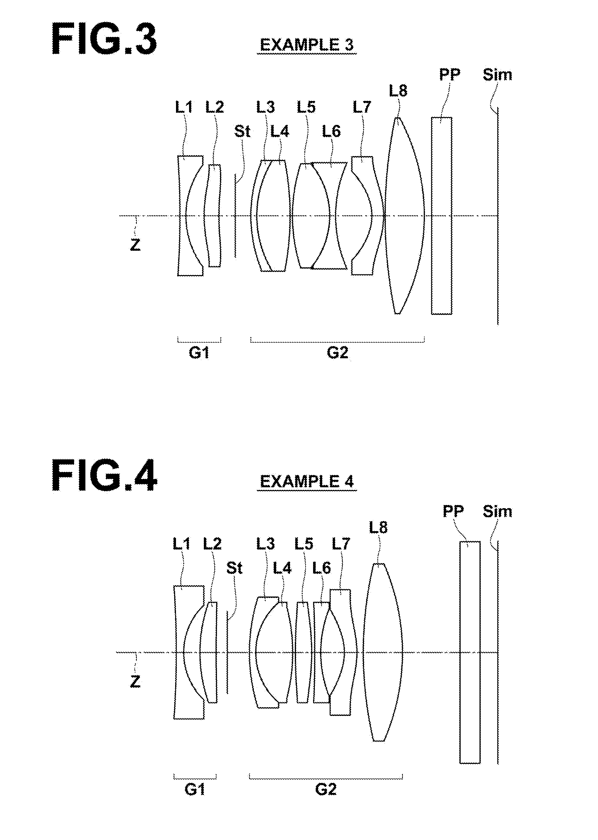
[0140]FIG. 3 illustrates the arrangement of lens groups in the imaging lens of Example 3. The imaging lens of Example 3 has approximately the same configuration as the imaging lens of Example 1 described above. However, the imaging lens of Example 3 differs from the imaging lens of Example 1 in the three points that a second lens L2 is a positive meniscus lens having a convex surface toward the object side, that a sixth lens L6 is a biconcave lens, and that a fifth lens L5 and the sixth lens L6 are cemented together.
[0141]In the present example, the second lens group G2 is constituted by a cemented lens formed by a third lens L3 and a fourth lens L4, a cemented lens formed by the fifth lens L5 and the sixth lens L6, a seventh lens L7 as the lens B, and an eighth lens L8 as the lens A, provided in this order from the object side. The configuration of the imaging lens of the present example, in which two pairs of cemented lenses are provided in the manner described above, is advantage...
PUM
 Abstract
Description
Claims
Application Information