Electric oil pump and hydraulic pressure supply device

a technology of hydraulic pressure supply and electric oil pump, which is applied in the direction of machines/engines, liquid fuel engines, positive displacement liquid engines, etc., can solve the problems of affecting pumping properties and achieve the effect of increasing heat radiation capacity

Active Publication Date: 2014-08-28
DENSO CORP
View PDF9 Cites 18 Cited by
  • Summary
  • Abstract
  • Description
  • Claims
  • Application Information

AI Technical Summary

Benefits of technology

[0004]It is an object of the present invention to provide an electric oil pump and a hydraulic pressure supply device having an increased heat radiation capacity.

Problems solved by technology

When heat is transmitted from the stator to the pump rotor, the pumping properties may be affected.

Method used


Image

  • Electric oil pump and hydraulic pressure supply device
  • Electric oil pump and hydraulic pressure supply device
  • Electric oil pump and hydraulic pressure supply device

Examples


Embodiment Construction

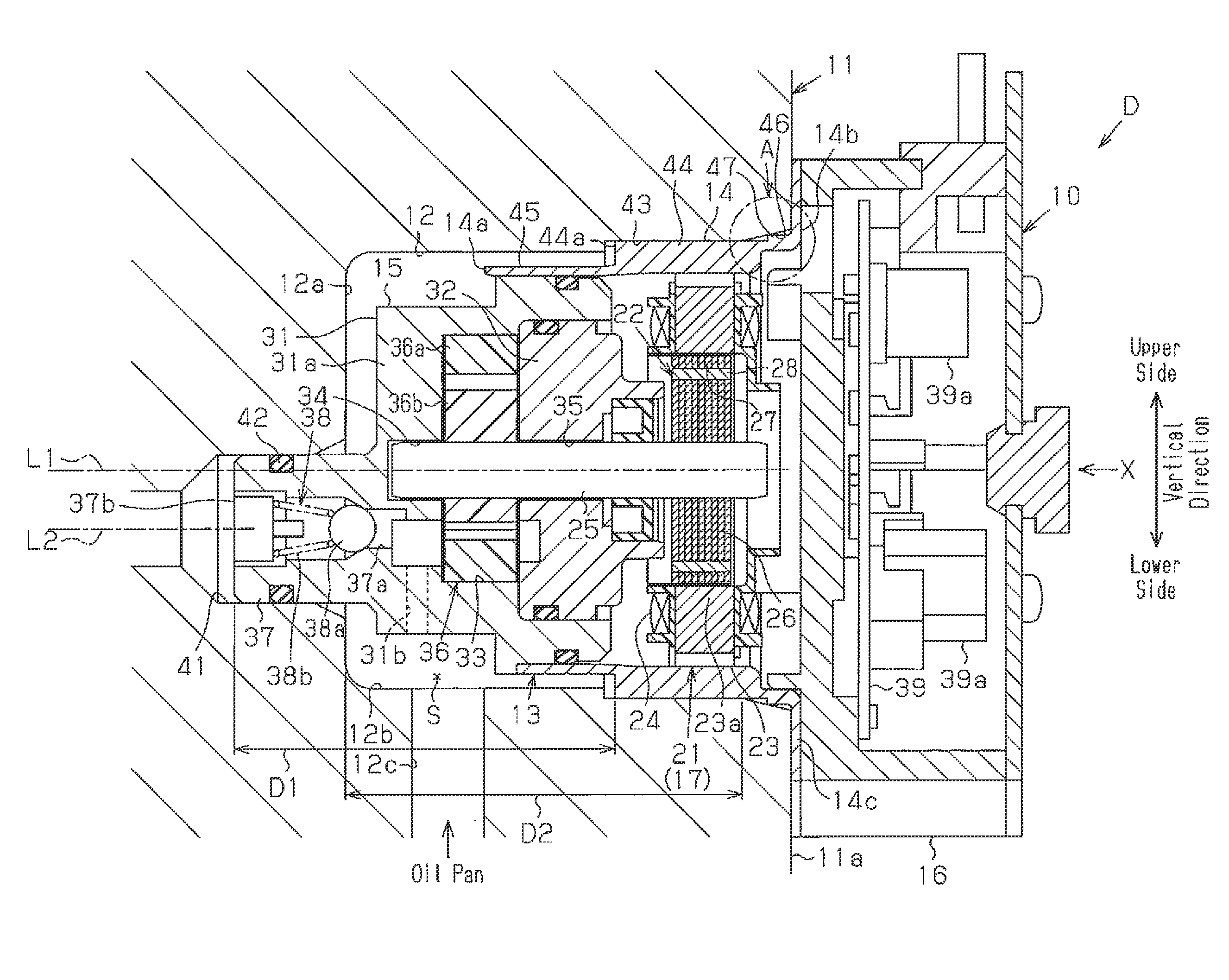
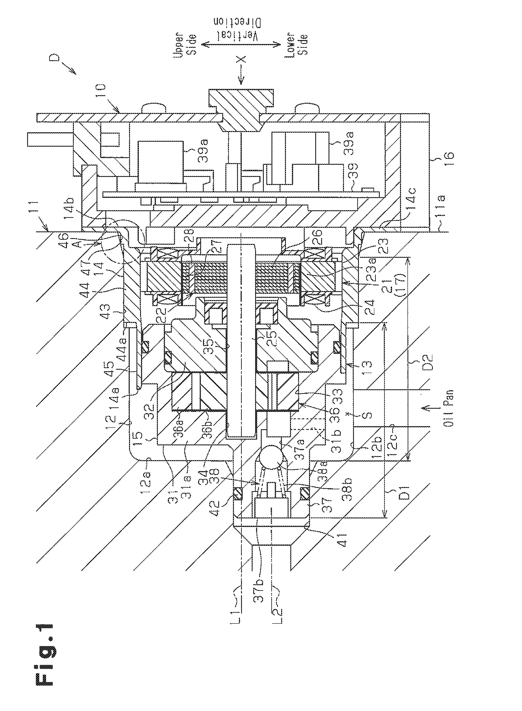
[0015]One embodiment of a hydraulic pressure supply device including an electric oil pump will now be described.

[0016]Referring to FIG. 1, an electric oil pump 10 of the present invention is used for a transmission 11 (drive force transmission device) of a vehicle. The electric oil pump 10 is coupled to the transmission 11 so that the electric oil pump 10 is partially fitted in a pump receptacle 12, which is located in the transmission 11. The electric oil pump 10 and the pump receptacle 12 form a hydraulic pressure supply device D of the transmission 11.

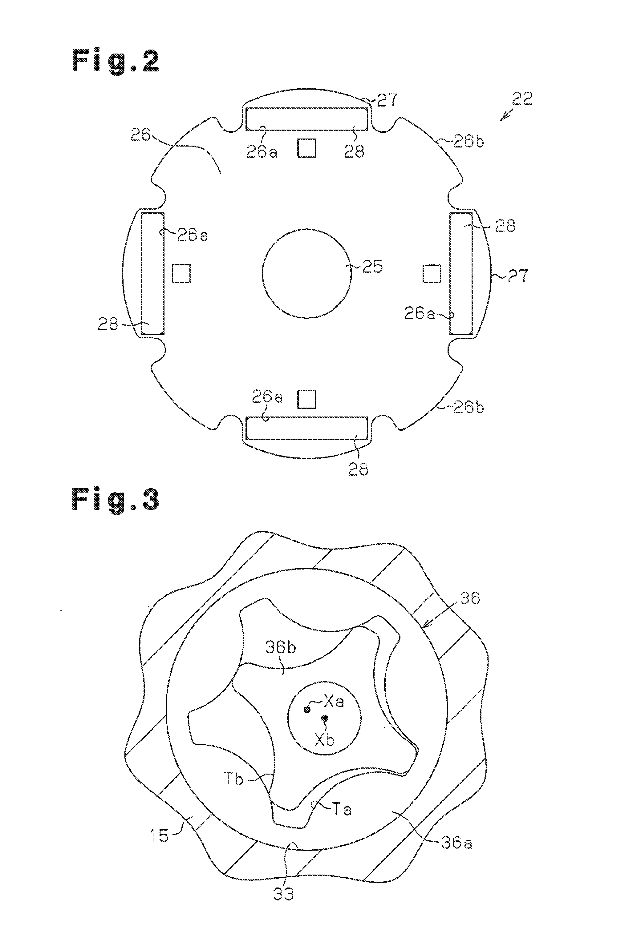
[0017]The electric oil pump 10 includes a housing 13. The housing 13 includes a tubular motor case 14, a pump case 15 arranged in one axial end (first end 14a) of the motor case 14, and a circuit case 16 arranged in the other axial end (second end) of the motor case 14. The portion of the electric oil pump 10 received in the pump receptacle 12 forms a portion of the housing 13 (fitted portion). In the present embodiment, the fitted ...


PUM


Abstract

An electric oil pump is coupled to a pump receptacle including an oil inflow passage and an oil outflow passage. The electric oil pump includes a motor, a pump rotor, a housing, and a check valve. The housing accommodates the motor and the pump rotor. The housing closes an opening of the pump receptacle and includes at least a fitted portion fitted into the pump receptacle. An oil compartment is formed between the pump receptacle and the housing. Oil flows into the oil compartment from the oil inflow passage when the pump rotor is rotated. The fitted portion is partially immersed in the oil collected in the oil compartment. The housing includes a suction port and a discharge port. A check valve, located in the housing, limits reversed flow of the oil from the oil compartment to the oil inflow passage.

Description

BACKGROUND OF THE INVENTION[0001]The present invention relates to an electric oil pump and a hydraulic pressure supply device that are arranged in, for example, a transmission of a vehicle.[0002]Japanese Laid-Open Patent Publication No. 2011-94553 describes an example of an electric oil pump that includes a motor, a pump rotor driven and rotated by the motor, and a housing accommodating the motor and the pump rotor. The housing is partially fitted into a pump receptacle of a vehicle transmission so that the housing closes the pump receptacle. The housing includes an inlet and an outlet through which oil is drawn in and discharged when the pump rotor rotates. As the pump rotor rotates, oil is drawn into the oil pump through the inlet from an oil inflow passage in the pump receptacle. Further, oil is discharged from the oil pump through the outlet and into an oil outflow passage in the pump receptacle.[0003]In such an electric oil motor, the motor, especially, a stator of the motor is...

Claims


Application Information

Patent Timeline
Patent Type & Authority Applications(United States)
IPC IPC(8): F04C29/02F04C13/00
CPCF04C29/028F04C13/002F04C2/102F04C11/008F04C15/0096F04C2210/206F04C15/06F04C13/001
Inventor SUZUKI, MOTOTSUGUIRIE, MASARU
Owner DENSO CORP
Why Eureka
Try Eureka