

Electric floating ball valve
a floating ball valve and electric technology, applied in the direction of valve details, valve arrangements, valve members for heating/cooling, etc., can solve the problems of electric control valves that do not display a good performance, take a great amount of energy, and the case is still getting more and more serious, and achieves simple structure and high stability in use.
- Summary
- Abstract
- Description
- Claims
- Application Information
AI Technical Summary
Benefits of technology
Problems solved by technology
Method used
Image

Examples
Embodiment Construction
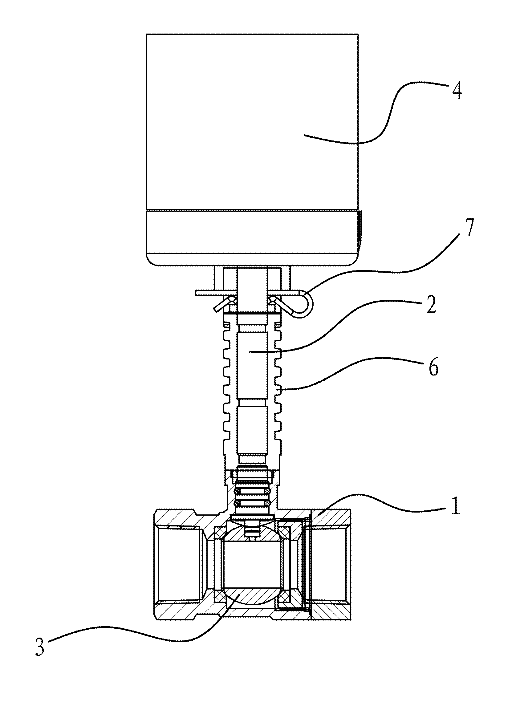
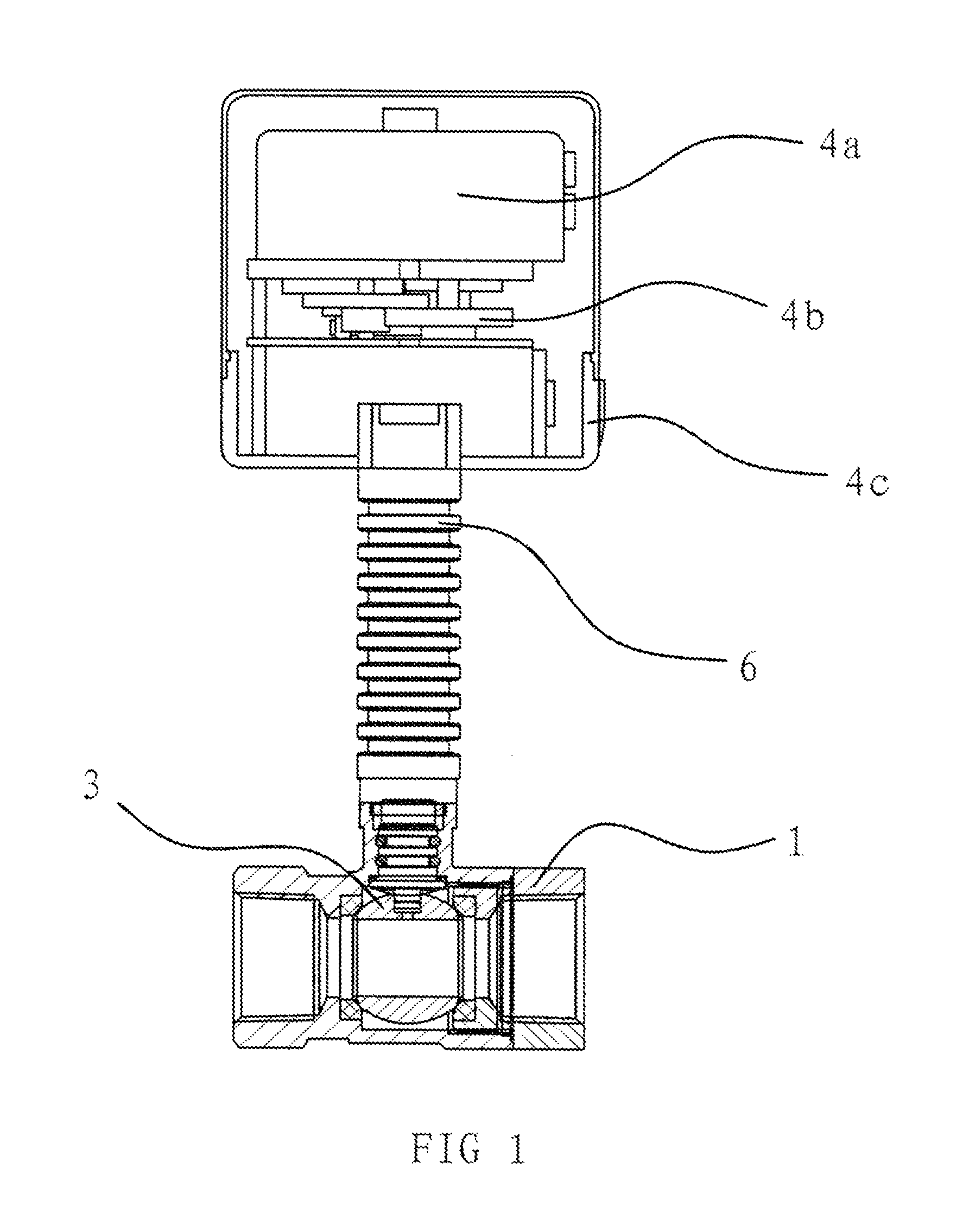
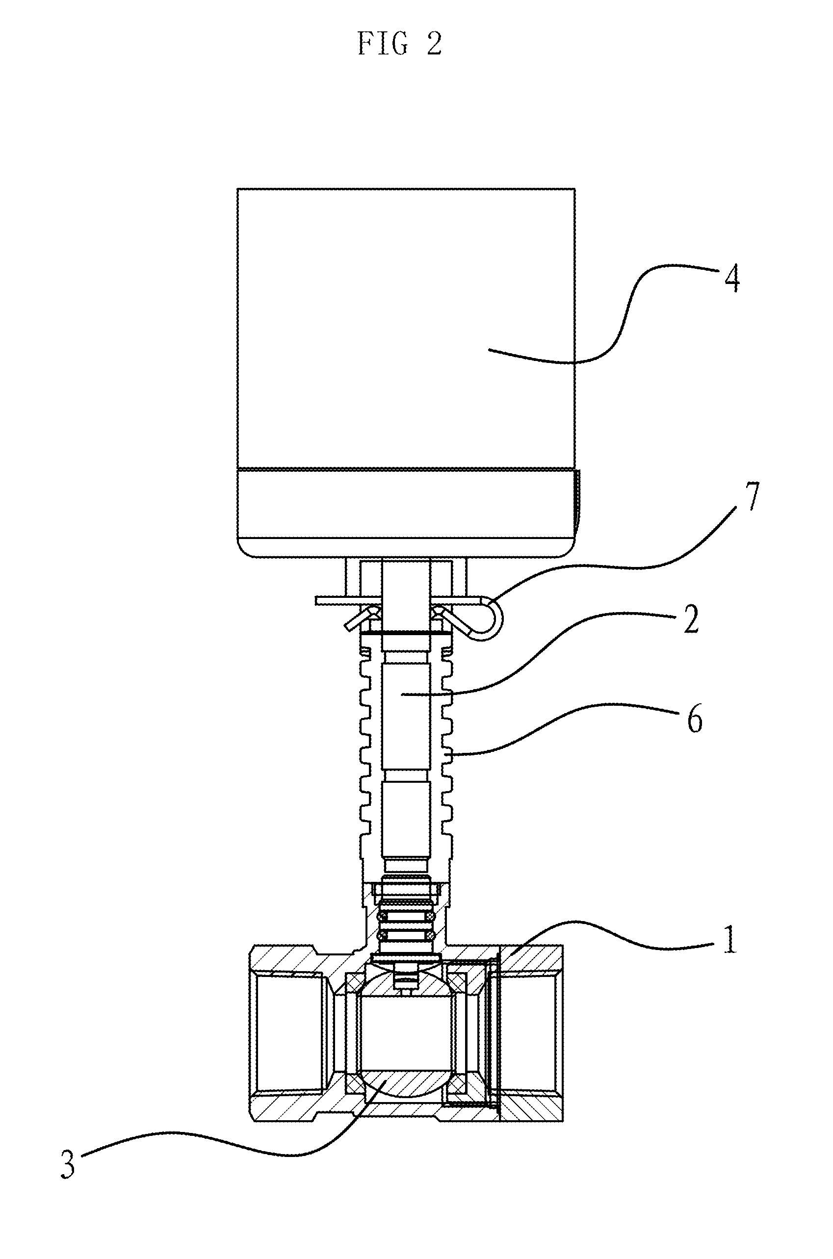
[0054]As shown in FIG. 1, the electric floating ball valve of the invention is mounted in the steam pipeline system, including a valve body 1, a valve stem 2, a valve core 3 and a drive mechanism 4.
[0055]As shown in FIGS. 1, 2 and 3, the valve core 3 is positioned within the valve body 1, the drive mechanism is positioned outside the valve body 1, and the valve stem 2 passes through the valve body 1 and the inner end of the valve stem 2 is linked with the valve core 3. In this embodiment, a gasket 5 is provided between the valve core 3 and the valve body 1. An extending through hole 3a for passing the medium is provided at the center of the valve core 3. A pressure discharge hole 3b is set in the valve core 3, for communicating the through hole 3a with the internal cavity of the valve body 1.
[0056]The drive mechanism 4 includes a housing 4c, a motor 4a provided within the housing and a transmission gear unit 4b, in which the motor 4a is connected with the input end of the transmissi...
PUM
 Abstract
Description
Claims
Application Information