Ceiling radiation system

A radiant system and ceiling technology, applied in air conditioning systems, household heating, lighting and heating equipment, etc., can solve problems such as the obstruction of cooling effect of heat pipes, and achieve the effect of improving performance and efficient cooling

Active Publication Date: 2007-10-10
青木住宅机材贩卖株式会社
View PDF0 Cites 4 Cited by
  • Summary
  • Abstract
  • Description
  • Claims
  • Application Information

AI Technical Summary

Problems solved by technology

However, in this way, the cooling effect of multiple cooling pipes will be hindered by the connecting plate

Method used


Image

  • Ceiling radiation system
  • Ceiling radiation system
  • Ceiling radiation system

Examples


Embodiment Construction

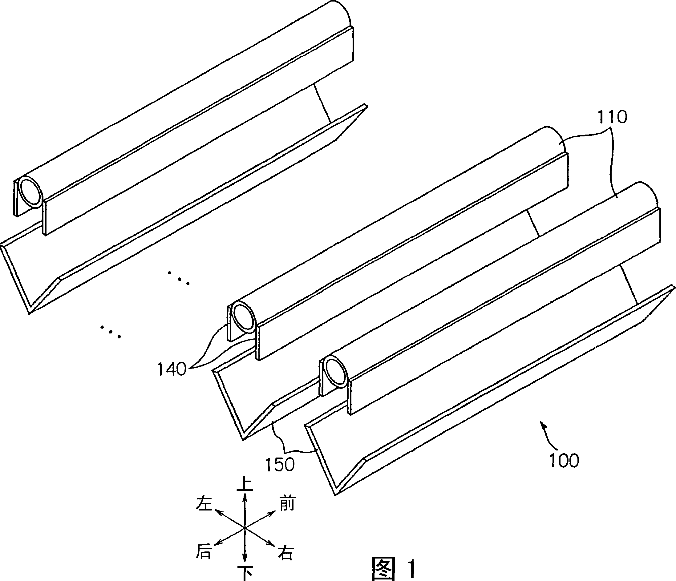
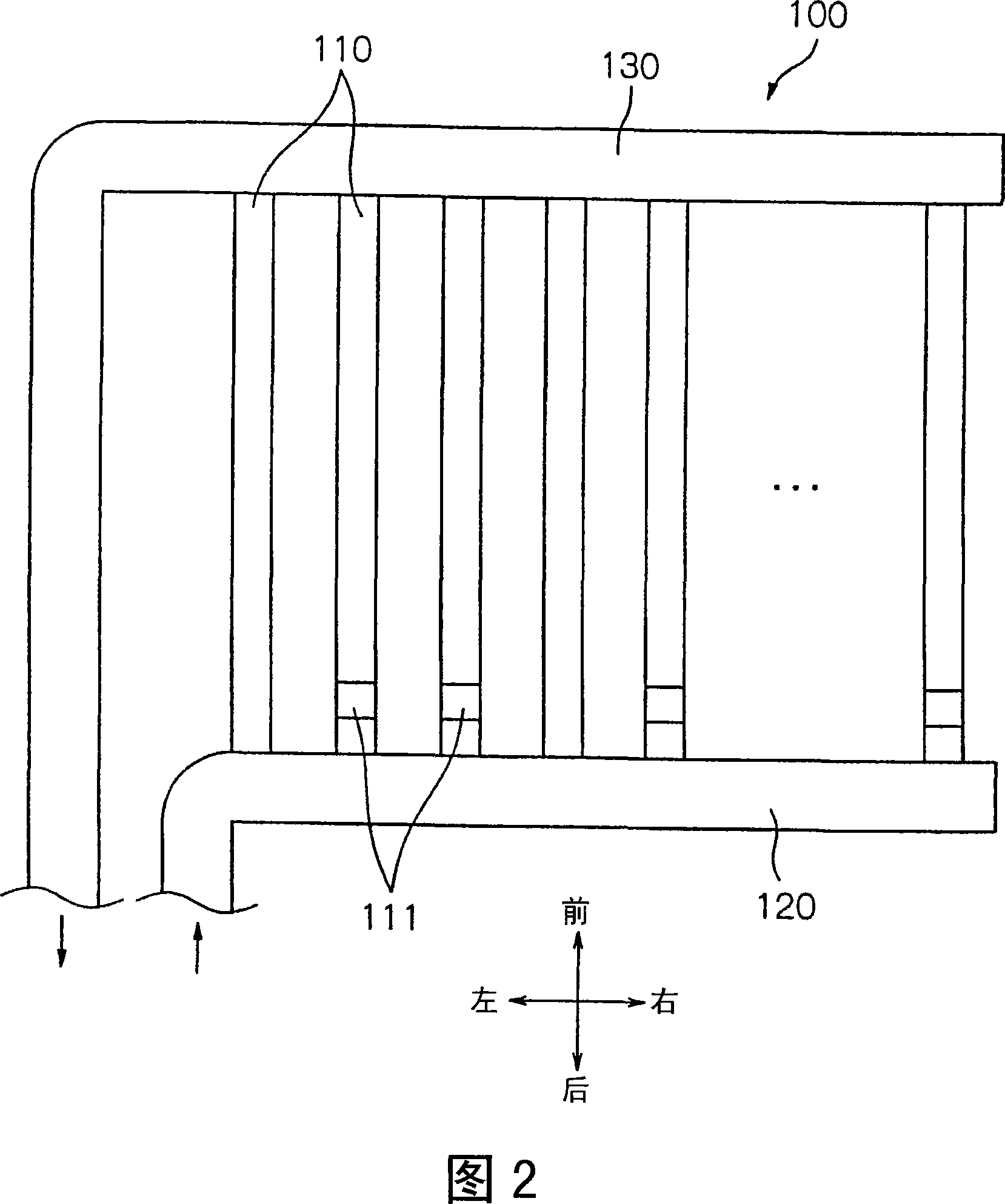
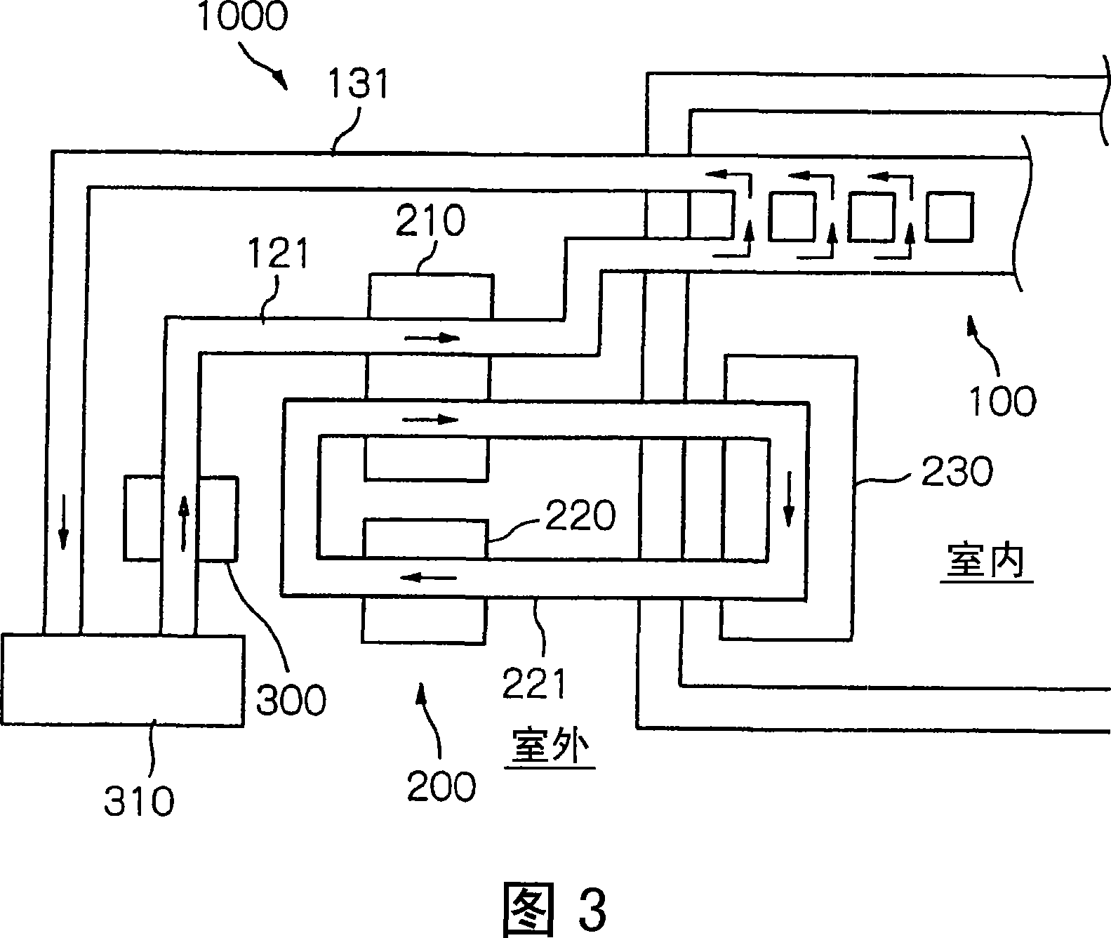
[0023] Hereinafter, an embodiment of the present invention will be described with reference to the drawings. As shown in FIG. 3 , a ceiling radiation system 1000 according to the present embodiment includes a ceiling unit 100 , a cold water generation mechanism 200 , a pump device 300 as a cold water flow mechanism, and the like. As shown in FIGS. 1 and 2 , the ceiling unit 100 is composed of a plurality of heat dissipation pipes 110 , a water supply pipe 120 , a recovery pipe 130 , a plurality of heat dissipation plates 140 , and a plurality of drainage grooves 150 .

[0024] The water supply pipe 120 and the recovery pipe 130 are composed of elongated copper pipes with an outer diameter of 30 mm and a wall thickness of 2.0 mm, for example, and are formed to have a predetermined overall length corresponding to the ceiling surface. The heat radiation pipe 110 is made of, for example, an elongated copper pipe with an outer diameter of 20 mm and a wall thickness of 2.0 mm, and i...


PUM


Abstract

A ceiling radiation system for carrying out indoor refrigeration is prepared for making cold water flow in multiple heat radiation tube for carrying out indoor refrigeration through heat radiation of heat radiation tubes and plates, condensing water on surfaces of heat radiation tubes and plates when cooled water is flowed in said heat radiation tube and plates, recovering condensed water through water drainage groove for increasing refrigeration performance.

Description

technical field [0001] The present invention relates to a ceiling radiant system which utilizes radiant heat to cool a room, in particular to a ceiling radiant system which makes cold water flow in heat dissipation pipes arranged near the ceiling surface of the room. Background technique [0002] At present, the mainstream air-conditioning system cools the air drawn from indoors or outdoors and supplies it indoors. However, since the indoor air temperature does not correspond to the radiant heat, the human body feels unnatural. Therefore, a refrigeration system has been developed that cools a room using radiant heat by flowing cold water through heat radiation pipes disposed in the room. [0003] Such refrigeration systems include: a wall-shaped radiation system, which arranges heat dissipation pipes in a wall shape, and arranges a drain tank for receiving dew condensation water below (for example, refer to Non-Patent Document 1); and a ceiling radiation system, which dissi...

Claims


Application Information

Patent Timeline
Patent Type & Authority Applications(China)
IPC IPC(8): F24F3/06
Inventor 青木宪明龟井昭宏土井岩渡边忍须永修通藤江创
Owner 青木住宅机材贩卖株式会社
Why Eureka
Try Eureka