System and method for dual mode stylus detection

a dual-mode, stylus technology, applied in the direction of instruments, electric digital data processing, computing, etc., can solve the problems of increasing variability, introducing some errors in position detection, and degrading the detection coil of the stylus, so as to improve the accuracy of detection, improve the accuracy of prior art, and quickly and accurately pinpoint the actual location

Inactive Publication Date: 2014-09-04
NOOK DIGITAL
View PDF11 Cites 24 Cited by
  • Summary
  • Abstract
  • Description
  • Claims
  • Application Information

AI Technical Summary

Benefits of technology

[0021]The system and method of the present provide for improved accuracy in the detection of a stylus on a touch sensitive surface of an electronic device, such as a tablet. The system and method employ a dual method of detection that compliments each other to form a detection system can increase accuracy of the prior art several fold (e.g., 2 mm vs 0.2 mm) First a electromagnetic induction detection system provides a coarse (e.g., + / −2 mm) coordinate of the location of a stylus with respect to a screen of the electronic device. The course stylus coordinate is then used in the processing of a capacitive detection system that performs a subpanel capacitive scanning for the pen tip as it contacts the touch screen in the vicinity of the course stylus coordinate. The subpanel capacitive scanning yields the final stylus coordinate that is significantly (e.g., 1000%) more precise than that of the prior art.
[0022]Specifically, the electronic device detects the presence of the top of the stylus and provides the general coordinates of its position. Then, as touches occur on the surface of the device, e.g., the stylus tip as well as the various parts of the user's hand, the system uses the coordinates supplied from the electromagnetic induction detection to very quickly and accurately pinpoint the actual location of the stylus input on the surface of the device.

Problems solved by technology

The tilt of the stylus may thus introduce some error in the position detection.
Further, near the edge of any device using pen input, the detection of the coil in the stylus degrades due to blocking of the signal by the frame of the device and increased variability of where the tip may actually lie on the surface of the device.
Disadvantages include the need to press down on the screen, and a risk of damage by sharp objects.
Resistive touchscreens also suffer from poorer contrast, due to having additional reflections from the extra layer of material placed over the screen.
As the human body is also an electrical conductor, touching the surface of the screen results in a distortion of the screen's electrostatic field, measurable as a change in capacitance.
Unlike a resistive touchscreen, one cannot use a capacitive touchscreen through most types of electrically insulating material, such as gloves.
This disadvantage especially affects usability in consumer electronics, such as touch tablet PCs and capacitive smartphones in cold weather.
As it has no moving parts, it is moderately durable but has limited resolution, is prone to false signals from parasitic capacitive coupling, and needs calibration during manufacture.
Conductive smudges and similar interference on the panel surface can interfere with the performance.
Collected dust, which adheres to the screen due to the moisture from fingertips, can also be a problem.
This method produces a stronger signal than mutual capacitance, but it is unable to resolve accurately more than one finger, which results in “ghosting”, or misplaced location sensing.

Method used


Image

  • System and method for dual mode stylus detection
  • System and method for dual mode stylus detection
  • System and method for dual mode stylus detection

Examples


Embodiment Construction

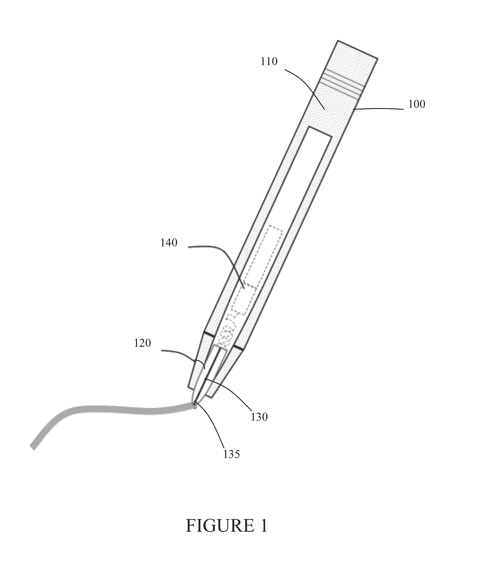
[0030]FIG. 1 illustrates a stylus 100 according to the present invention. The stylus includes a body 110 which is pen shaped for easy and comfortable holding by a user. Within the body 110 is a stylus tip 130. Tip 130 is preferably made from an optically clear and electrically conductive material. In a preferred embodiment, the tip is optically clear so that it can include a colored indicator line 130 that serves to aid the user in identifying and locating the actual tip 135 of the pen tip 120, which is the point where the stylus 100 actually contacts the surface of an electronic device.

[0031]Also included in body 140 is the electromagnetic induction circuitry 140 used to assist in the detection of the location of the pen tip 120 in relation to the surface of the electronic device. Typically, this electromagnetic induction circuitry 140 is formed from an inductor and a capacitor (LC) circuit. The LC circuit will resonate at a particular frequency when energized. Another form of elec...


PUM


Abstract

A system and method for improved accuracy in the detection of a stylus on a touch sensitive surface of an electronic device, such as a tablet. A dual method of detection is employed including electromagnetic induction detection of the stylus as it is in the vicinity of the screen of the electronic device, as well as capacitive detection of the stylus tip as it contacts the touch screen. The electronic device detects the presence of the top of the stylus and provides the general coordinates of its position. Then, as touches occur on the surface of the device, e.g., the stylus tip as well as the various parts of the user's hand, the system uses the coordinates supplied from the electromagnetic induction detection to very quickly and accurately pinpoint the actual location of the stylus input on the surface of the device.

Description

FIELD OF THE INVENTION[0001]The present invention generally relates to devices for detecting user input on an electronic device, and more particularly to systems and methods for improved detection of a stylus on a touch sensitive surface of an electronic device.BACKGROUND OF THE INVENTION[0002]Electronic devices such as cellular phones, eReaders, and tablets are fast becoming necessities, especially for people on the move. Electronic devices can be used to place phone calls, to text messages, read electronic publications to browse the Internet, to take pictures and the like.[0003]Digitizing tablet systems are well known in the art and are used in a variety of applications, e.g., note taking. These systems generally include a tablet, a position indicating implement such as a pen or stylus and the associated electronics for producing some form of interaction between the stylus and the tablet from which is derived digital data signals representing the position of the stylus on the tabl...

Claims


Application Information

Patent Timeline
Patent Type & Authority Applications(United States)
IPC IPC(8): G06F3/044
CPCG06F3/044G06F3/0346G06F3/0354G06F3/046G06F3/0441G06F3/0442
Inventor CHANG, SONGAN ANDY
Owner NOOK DIGITAL
Why Eureka
Try Eureka