
Disaster recovery failover in cloud computing

a cloud computing and disaster recovery technology, applied in the field of replicating resources, can solve the problems of difficult to create a replica that offers the same functionality as the original web hosting system, and the web designer cannot decide how much computing power is necessary

Inactive Publication Date: 2014-09-04
UNITRENDS
View PDF5 Cites 20 Cited by
  • Summary
  • Abstract
  • Description
  • Claims
  • Application Information

AI Technical Summary

Benefits of technology

The invention provides a system that allows for the efficient management and configuration of target resources through an association between the target resource identifier and the source resource identifier. This allows for the replication of the source resource in the target cloud, even if the target cloud does not provide an image with the same identifier. The same level of security is achieved in the target cloud as in the source cloud by replicating the association of instances to security groups. The technical effects of this invention include improved efficiency, reliability, and security in resource configuration.

Problems solved by technology

It is difficult for the web designer to decide how much investment into computing power is necessary to provide reliable web presence.
However, it is difficult to create a replica that offers identical functionality to the original web hosting system 200.

Method used


Image

  • Disaster recovery failover in cloud computing
  • Disaster recovery failover in cloud computing
  • Disaster recovery failover in cloud computing

Examples


Embodiment Construction

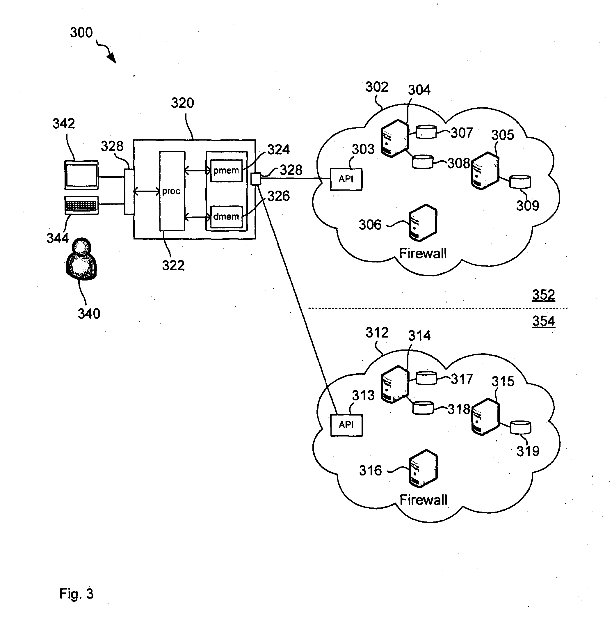
[0076]FIG. 3 illustrates a computer network 300 comprising a source cloud 302, comprising application programming interface (API) 303 and source resources 304 to 309, and a target cloud 312, also comprising an API 313 and target resources 314 to 319, connected to a controller 320, via a data communication network, such as the Internet (not shown). In this example, the controller 320 is separate or remote from the source cloud 302 and the target cloud 312. In other examples, the controller 320 may be implemented within the source cloud 302 or the target cloud 312, that is, a computing instance accesses program code that is stored on a storage volume in that cloud to perform the steps described below.

[0077]In order to achieve a greater reliability in case of great disasters, the functionality of the source cloud 302 is replicated in the target cloud 312. This replication is performed by controller 320 as will be described below.

[0078]Controller 320 comprises processor 322 connected to...


PUM


Abstract

This disclosure relates to creating a resource and for configuring a resource (314) in cloud computing. A processor receives a source resource identifier of a source resource (304) in a source cloud (302) and sends a request to create a target resource (314) in the target cloud (312). The processor then receives a target resource identifier of the created target resource (314) and stores an association (500) between the target resource identifier (504) and the source resource identifier (502). Using the stored association allows to determine a target resource identifier for a resource identifier and therefore configuration of target resources, where the configuration depends on target resource identifiers.

Description

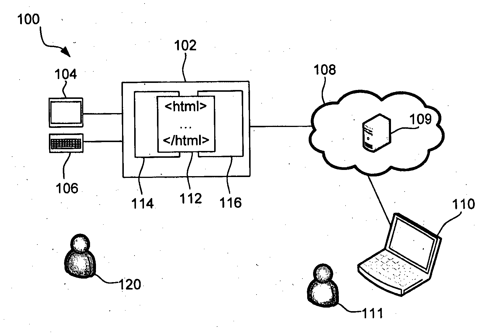
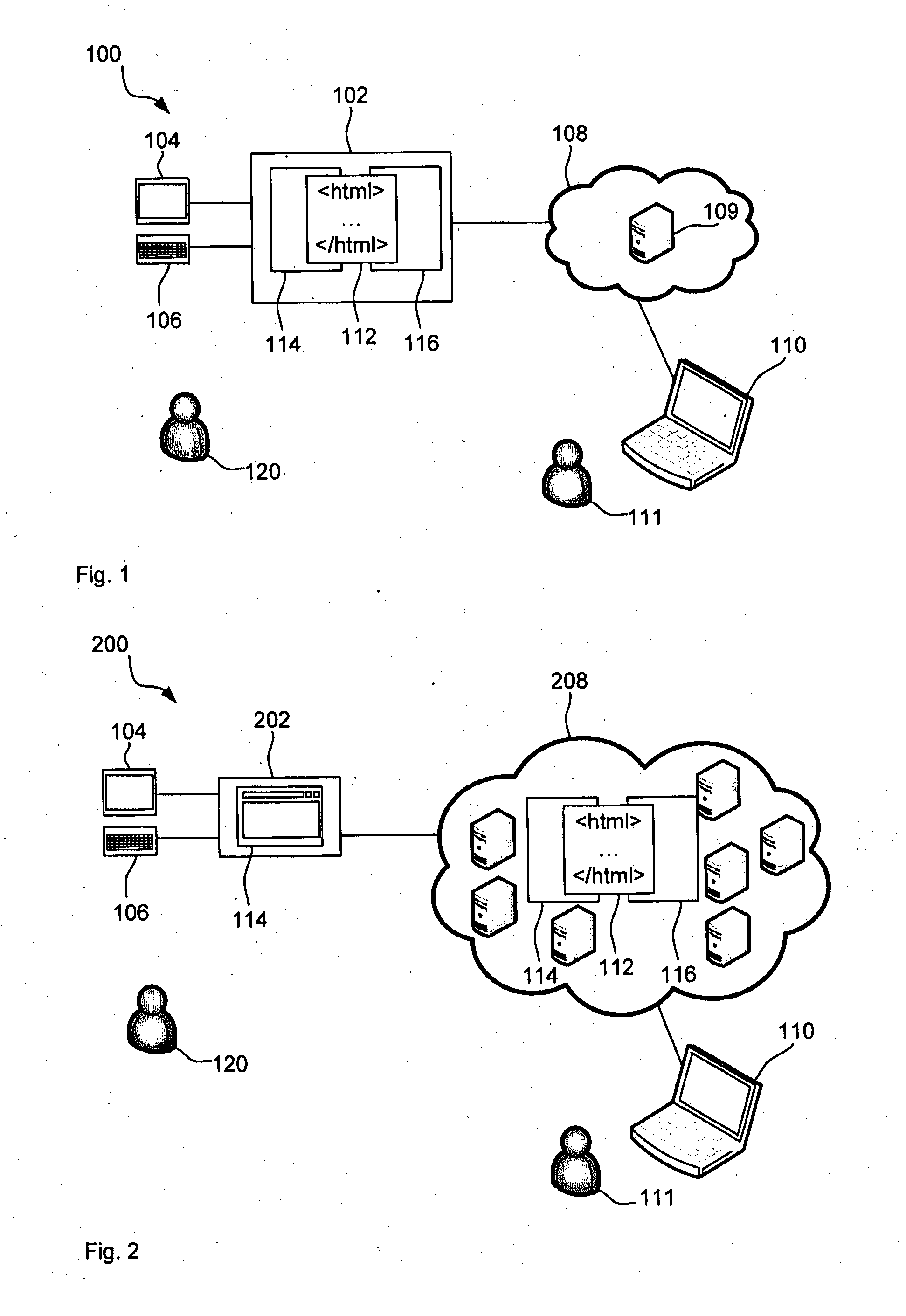
CROSS-REFERENCE TO RELATED APPLICATIONS [0001]The present application claims priority from Australian Provisional Patent Application No 2011904266 filed on 14 Oct. 2011, the content of which is incorporated herein by reference.TECHNICAL FIELD [0002]This disclosure generally relates to replicating resources in a cloud computing environment. In particular, but not limited to, it relates to a methods, systems and software for creating a resource and for configuring a resource.BACKGROUND ART [0003]Cloud computing has changed many workflows related to the Internet. The differences between traditional server-based web hosting and web-services in the cloud will, now be described with reference to a simple example.[0004]FIG. 1 illustrates a server-based web-hosting system 100 comprising a server 102 connected to a display 104, an input device 106, such as a keyboard, and a computer network 108, such as the Internet comprising a domain name service (DNS) server 109. A computer 110 of a user ...

Claims


Application Information

Patent Timeline
IPC IPC(8): H04L12/24
CPCH04L41/0896G06F11/006G06F11/1662G06F11/2038G06F11/2048
Inventor LIU, ANNALEE, KEVINODOLPHI, JORKEWADA, HIROSHI
Owner UNITRENDS
Learn More