Floating manhole frame assembly

a manhole frame and assembly technology, applied in the direction of artificial islands, construction, building components, etc., can solve the problems of unbalanced movement of the surrounding structure, uneven surface, and many conventional manhole frame assemblies that cannot move in harmony with the ground or the surrounding structur

Inactive Publication Date: 2014-09-11
EAST JORDAN IRON WORKS
View PDF4 Cites 11 Cited by
  • Summary
  • Abstract
  • Description
  • Claims
  • Application Information

AI Technical Summary

Benefits of technology

[0005]The present invention provides a manhole frame assembly configured to seat about an opening of an underground area, and to be installed adjacent a surrounding structure. The manhole frame assembly may include a lower frame having a lower peripheral wall and a base, the base adapted to be fastened in place on the opening. The manhole frame assembly may also include an upper frame adapted to move with respect to the lower frame. Movement of the upper frame may occur in response to movements in the surrounding structure. In addition to or alternatively, movement of the upper frame may be conducted during installation to substantially match the upper frame height to the surface of the surrounding structure. By being capable of movement, the upper frame may provide a smooth transition between the surrounding surface and the manhole frame assembly.
[0006]The manhole frame assembly may also include a sleeve encircling at least part of the lower frame and capable of encircling at least part of the upper frame. The sleeve may prevent the surrounding structure from binding overlapping portions of the upper and lower frames so that the upper frame is capable of floating. And, the sleeve may be rigid such that it resists deflection in response to loading from the surrounding structure.
[0007]In one embodiment, the sleeve has a perimeter defining a gap between the sleeve and the lower peripheral wall, where the upper peripheral wall of the upper frame may fit within the gap. With this configuration, for example, portions of the upper frame may slide between the sleeve and the lower frame. The upper frame may displace vertically with respect to the lower frame, thereby extending and contracting within the gap. The upper frame may also tilt with respect to the lower frame. Because the upper frame may tilt, extend, and contract, the upper frame may float to maintain smooth transitions between a surface of the surrounding structure and the manhole frame assembly.
[0008]The gap formed by the sleeve may prevent the surrounding structure from binding the upper frame to the lower frame. For example, without the sleeve, the surrounding structure may sufficiently load the upper frame against the lower frame such that the upper frame is prevented from floating as intended. The sleeve may prevent such loading of the upper frame.
[0009]In one embodiment, the upper frame may include a projection extending from the upper peripheral wall that links with the surrounding structure. This link may enable movement in the surrounding structure to be translated to the upper frame, thereby resulting in the upper frame floating with respect to the lower frame to maintain appreciably smooth transitions between the surface of the surrounding structure and the frame assembly.
[0010]The present invention provides an effective manhole frame assembly that enables part of the frame assembly to move in response to movement in the surrounding structure. In this way, the manhole frame assembly may mitigate against abrupt transitions between the surface of the surrounding structure and the manhole frame assembly. These and other objects, advantages, and features of the present invention will be more fully understood and appreciated by reference to the description of the current embodiment and the drawings.

Problems solved by technology

Thus, even if the manhole frame assembly, when fitted with a cover, is installed flush with the surrounding surface (e.g., the road surface), shifts in the surrounding structure may result in an uneven surface.
Another event, soil erosion, may cause movement in the surrounding structure as well.
As mentioned previously, many conventional manhole frame assemblies are unable to move in harmony with the ground or the surrounding structure.
This inability to move is a common drawback of conventional manhole cover assemblies because it can result in a rough road surface or an abrupt transition between the surrounding surface and the manhole frame assembly.
Uneven features in the roadway may increase wear on any vehicles traveling over the roadway.

Method used


Image

  • Floating manhole frame assembly
  • Floating manhole frame assembly
  • Floating manhole frame assembly

Examples


Embodiment Construction

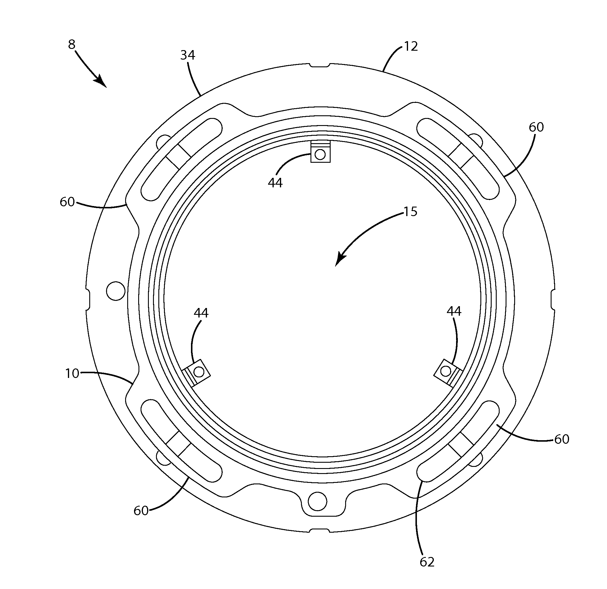
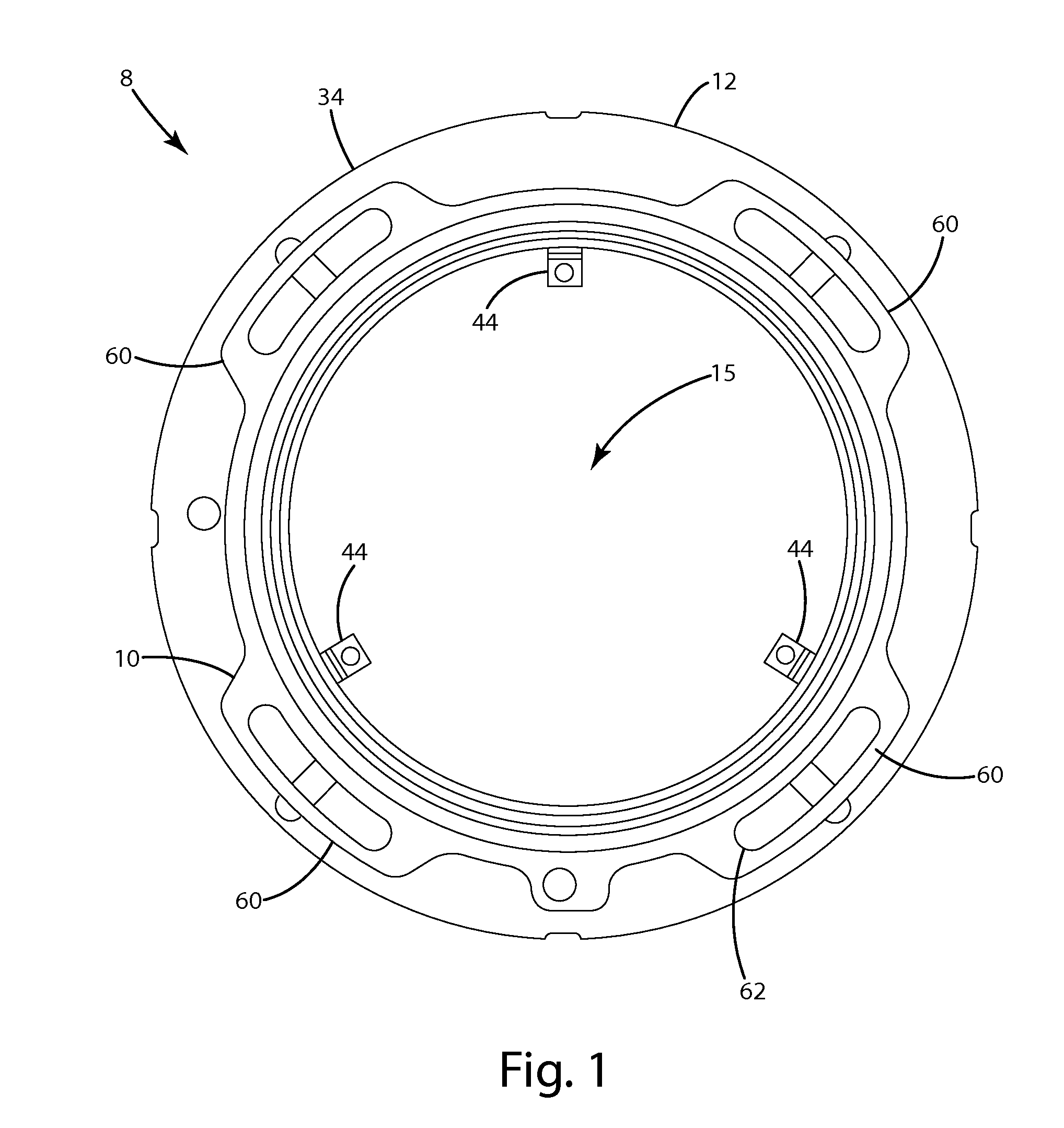
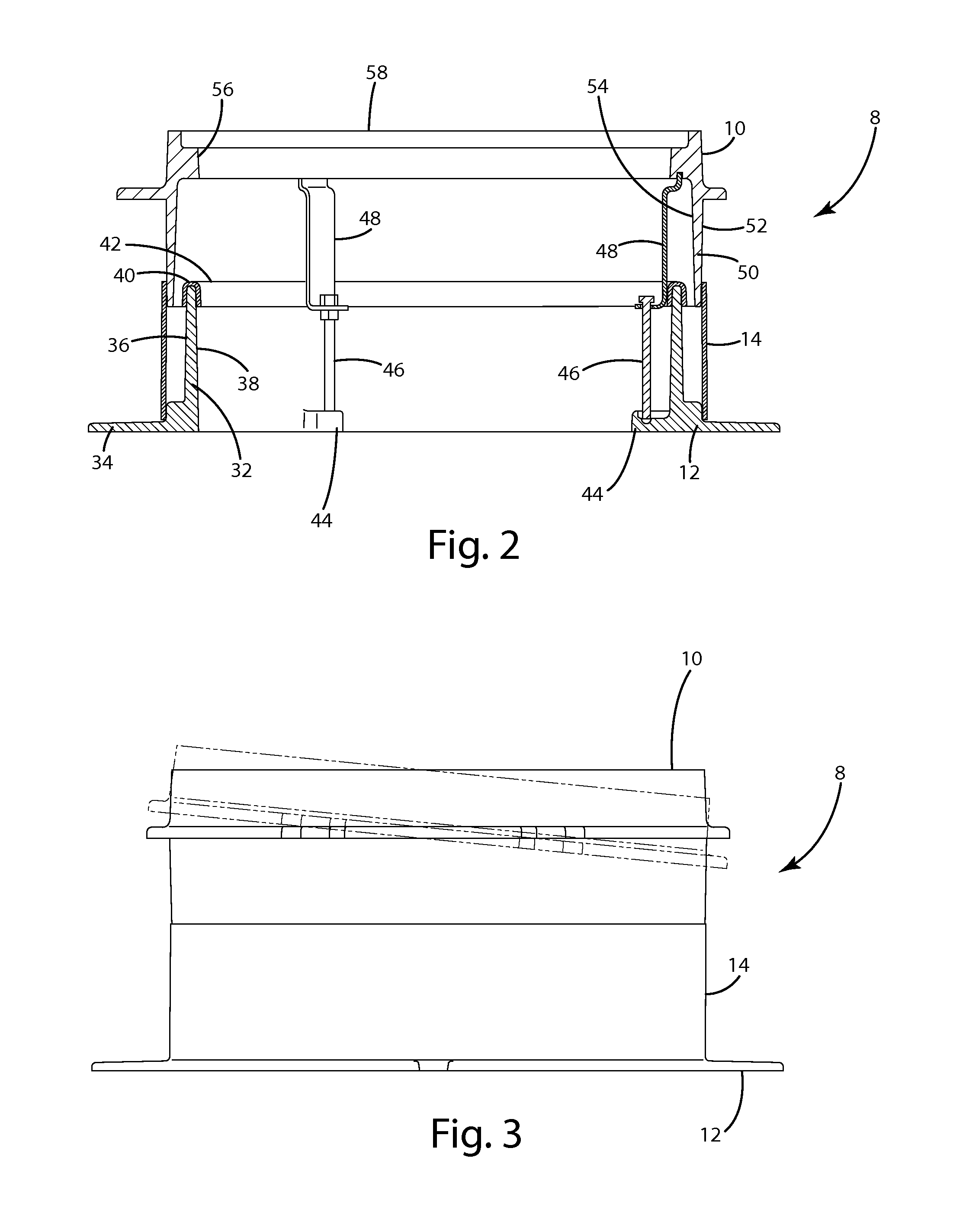
[0018]A manhole frame assembly according to one embodiment of the present invention is shown in FIGS. 1-6 and generally designated 8. The manhole frame assembly 8 generally includes an upper frame 10 and a lower frame 12, and is adapted to support a manhole cover (not shown). The upper frame 10 in the current embodiment is allowed to float with respect to the lower frame 12, enabling the upper frame 10 to move with respect to the lower frame 12 during installation or as the surrounding structure moves, and potentially preventing uneven transitions between the manhole frame assembly and the surface of the surrounding structure. The manhole frame assembly 8 also includes a sleeve 14 disposed around the perimeter of the upper frame 10 and the lower frame 12. This sleeve 14 may shield portions of the upper frame 10 and the lower frame 12 from the surrounding structure so that the surrounding structure does not significantly impede movement of the upper frame 10 with respect to the lower...


PUM


Abstract

A manhole frame assembly according to one embodiment of the present invention generally includes an upper frame and a lower frame, and is adapted to support a manhole cover. The upper frame may be allowed to float with respect to the lower frame, enabling the upper frame to move during installation, or as the surrounding structure moves, or both. By being capable of movement, the upper frame may potentially prevent uneven transitions between the manhole frame assembly and the surface of the surrounding structure.

Description

BACKGROUND OF THE INVENTION[0001]The present invention relates to a floating manhole frame assembly, and more particularly to a manhole frame assembly configured to move as the surrounding environment moves.[0002]Manhole frame assemblies are well known. Generally, a manhole frame assembly covers an opening providing access to an underground area also known as a manhole that may include utilities, pipes, cables and passages. The manhole frame assembly may be fitted with a cover to, among other things, prevent someone from falling in and to keep unauthorized persons out. Conventional manhole frame assemblies include a frame capable of receiving a cover that limits access to the manhole. The cover is a removable plate forming the lid over an opening in the frame through which the underground area may be accessed. The manhole cover seats on the frame, sometimes flush with the surface of a road. And, the frame, often times, is secured to the underground area or surrounding structure, suc...

Claims


Application Information

Patent Timeline
Patent Type & Authority Applications(United States)
IPC IPC(8): E02D29/14
CPCE02D29/1409
Inventor REYNOLDS, DEAN W.JOHNSON, JEREMY I.
Owner EAST JORDAN IRON WORKS
Why Eureka
Try Eureka