
Connector Device for a Telescoping Tent Pole

a technology of connecting device and tent pole, which is applied in the direction of rod connection, building type, construction, etc., can solve the problems of difficult and cumbersome repair, time-consuming factory assembly, and high cost of connecting assembly

Inactive Publication Date: 2014-09-11
JIN KI HO
View PDF0 Cites 6 Cited by
  • Summary
  • Abstract
  • Description
  • Claims
  • Application Information

AI Technical Summary

Benefits of technology

The present invention is a simple and cost-effective connector device for connecting tent poles together in a telescoping arrangement. It consists of a tubular member with a detent on its interior surface, a lower aperture for inserting a lower pole, and a top member with an upper aperture for inserting an upper pole. The detent securely snaps the lower pole into the tubular member to create a quick and easy connection.

Problems solved by technology

However, telescopic tent poles in prior art instant tents are often connected together by complicated connection assemblies having numerous parts.
Such connection assemblies are costly, time consuming to factory assemble, and difficult and cumbersome to repair.
Not only is the prior art tent fly connection aesthetically unappealing but there is also the possibility of damage to the tent fabric as the tent fabric is subject to tension created by the tent fly.
However, telescopic pole connection assemblies of the prior art are not suited for coupling other accessories such as a tent fly because the connection assembly is unable to withstand the tension exerted by the tent fly, thus causing the connection assembly to disengage from the pole, making the pole unstable.

Method used


Image

  • Connector Device for a Telescoping Tent Pole
  • Connector Device for a Telescoping Tent Pole
  • Connector Device for a Telescoping Tent Pole

Examples


first embodiment

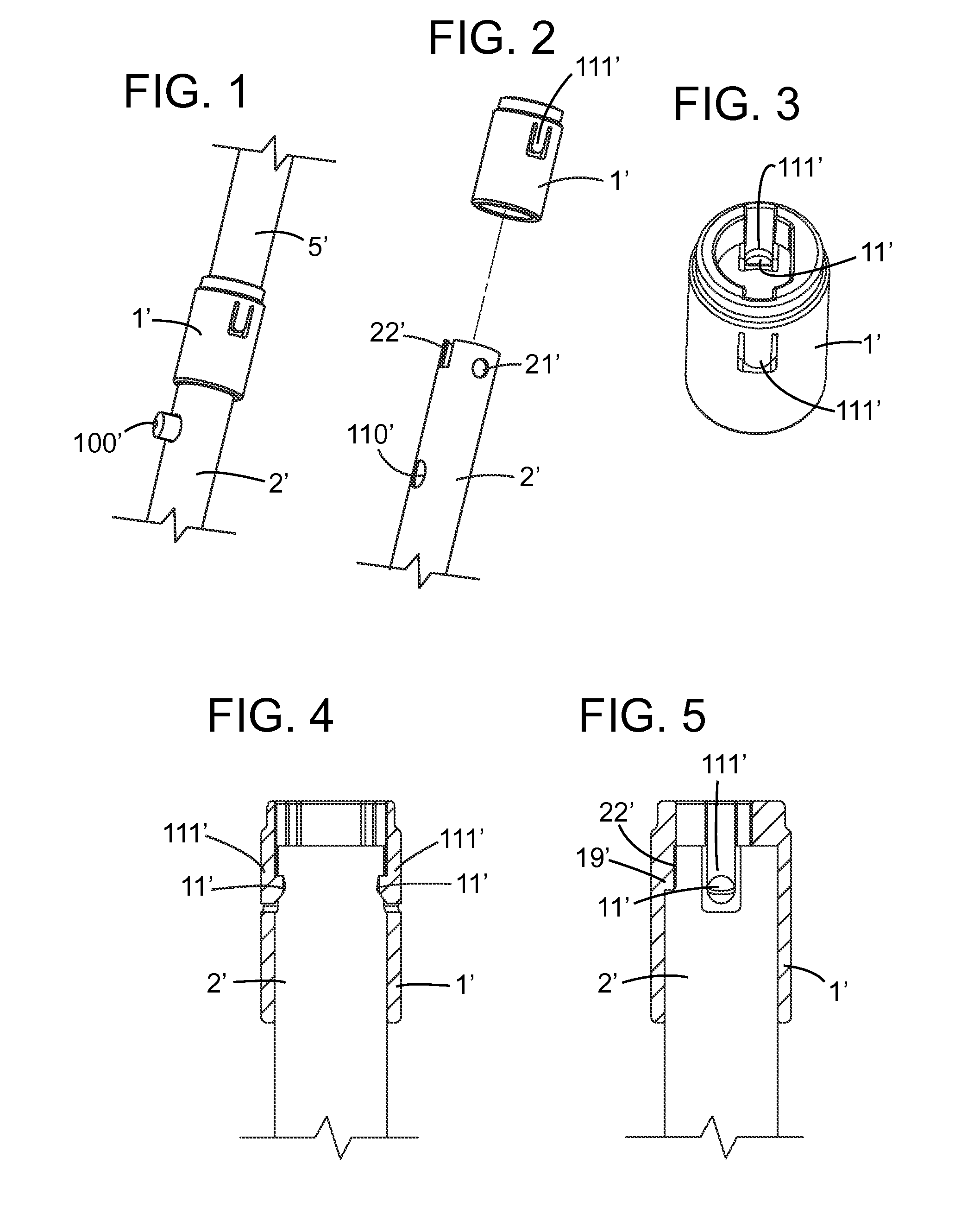
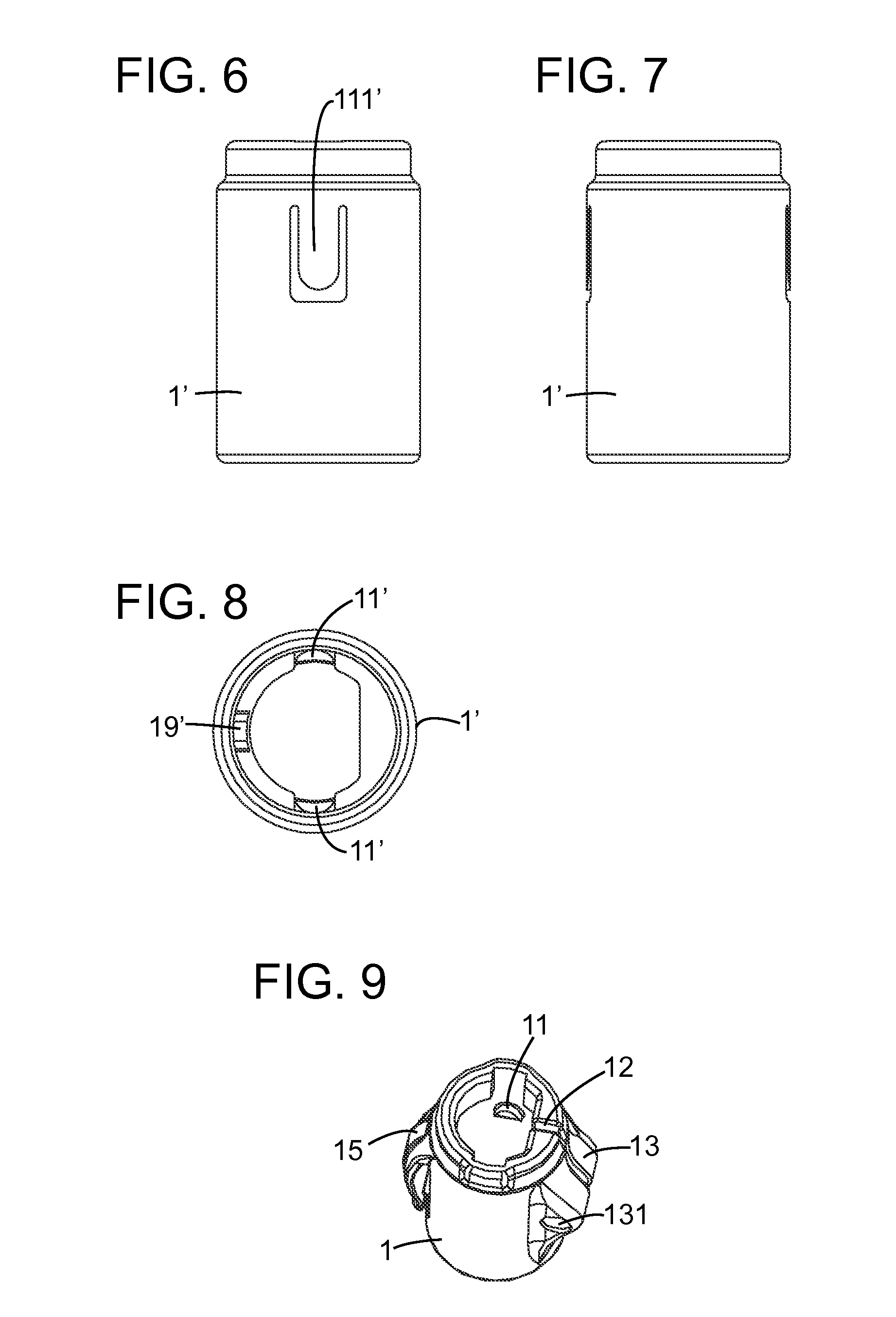
[0035]Referring to FIGS. 1-8, a connector device 1′ for a telescoping tent pole in the present invention is shown, in which the connector device 1′ includes a tubular member having an interior with an interior surface having at least one detent 11′ and a lower aperture for receiving a lower pole 2′ into the interior. A top member on the tubular member has an upper aperture for receiving an upper pole 5′ into the interior of the tubular member. The connector device 1′ is preferably manufactured by plastic injection molding and is one integral piece.

[0036]In the present embodiment, the lower pole 2′ is tubular steel having a circular cross-section and the upper pole 5′ is tubular steel having a generally semi-circular cross-section. The upper pole 5′ is sized such that it telescopes within the lower pole 2′, and the upper and lower apertures of the connector device 1′ are respectively sized and shaped for the same. One of ordinary skill in the art will recognize that the upper and low...

second embodiment

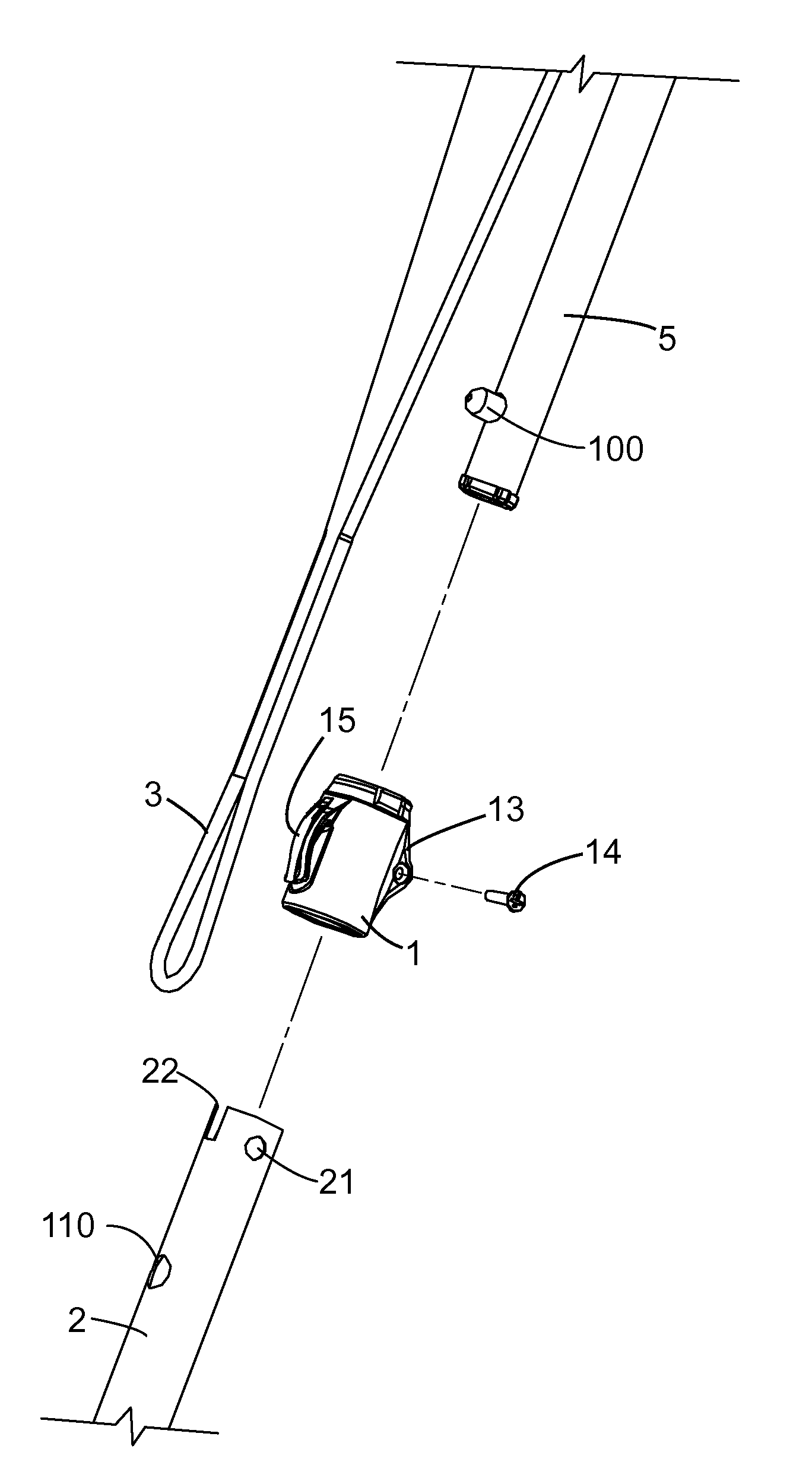
[0041]Referring to FIGS. 9-14, in the present invention, a connector device 1 for connecting a telescoping tent pole as well as for securing a tent fly 3 is shown. The connector device 1 is preferably constructed by injection molding plastic into one integral component. The interior of the connector device 1 has an interior surface having a pair of detents 11 extending laterally therefrom; a lower aperture for receiving a lower pole 2 into the interior; and a top member on the tubular member has an upper aperture for receiving an upper pole 5 into the interior of the tubular member. A longitudinal axis extends through the upper and lower apertures of the tubular member substantially parallel to the interior of the connector device 1. Also, the configuration of the upper and lower poles 5, 2 are substantially identical to the upper and lower poles 5′, 2′ described above.

[0042]Still referring to FIGS. 9-14, an outer surface of the connector device 1 includes a tent fly fastener 15 for...


PUM


Abstract

A connector device connects tent poles and includes a tubular member having an interior with an interior surface having a detent and a lower aperture for receiving a lower tent pole into the interior. A top member on the tubular member has an upper aperture for receiving an upper tent pole into the interior of the tubular member. The detent secures the lower tent pole to the tubular member in a snap-fit engagement and the upper pole is releasably lockable with the lower pole. Another connector device includes a tubular member having a longitudinal axis, and an outer surface having a tent fly fastener for fastening a tent fly, a slit extending parallel to the longitudinal axis, and a fastener receptacle to receive a fastener oriented perpendicular to the slit.

Description

CROSS-REFERENCE TO RELATED APPLICATIONS[0001]This application claims foreign priority to China Application Nos. 201320101781.4 and 201320101787.1, both filed on Mar. 6, 2013, which are incorporated by reference in their entireties.BACKGROUND OF THE INVENTION[0002]1. Field of the Invention[0003]The present invention relates to a mechanism for connecting tent poles, and more particularly to a connector device for telescopically connecting tent poles.[0004]2. Description of Prior Art[0005]Camping tents have evolved over the years to be more user-friendly. One of the features with constant improvement is the tent poles. Over the years, designers have eliminated the need to separately assemble and disassemble each pole section. This was first accomplished through the use of a shock cord or elastic rope that runs through the tent poles, allowing the pole sections to stay together when folded and then snap back into place to assemble the pole.[0006]More recently, instant tents—tents that a...

Claims


Application Information

Patent Timeline
Patent Type & Authority Applications(United States)
IPC IPC(8): E04H15/32
CPCE04H15/32E04H15/46E04H15/48E04H15/60F16B7/105
Inventor JIN, KI HO
Owner JIN KI HO
Learn More