Image processing apparatus, image capturing apparatus, image processing method, and storage medium

Active Publication Date: 2014-09-11
CANON KK
View PDF2 Cites 35 Cited by
  • Summary
  • Abstract
  • Description
  • Claims
  • Application Information

AI Technical Summary

Benefits of technology

[0015]According to the present invention, it is possible for a user to intuitively grasp th

Problems solved by technology

However, in the case where focusing is performed by specifying a specific subject, it is not possible for a user to grasp which subject other than the specific subject is brought into focus.
Further, by the technique disclosed in Japanese Patent Laid-Open No. 2010-177741, it is possible to grasp which subject is brought into focus by the map image in which marks indicating objects the image of which is to be captured are arranged in order in the depth direction, however, the map image is quite

Method used


Image

  • Image processing apparatus, image capturing apparatus, image processing method, and storage medium
  • Image processing apparatus, image capturing apparatus, image processing method, and storage medium
  • Image processing apparatus, image capturing apparatus, image processing method, and storage medium

Examples


first embodiment

[0053]Here, an aspect in which an image processing apparatus according to the present invention is applied to a digital camera is explained as a first embodiment.

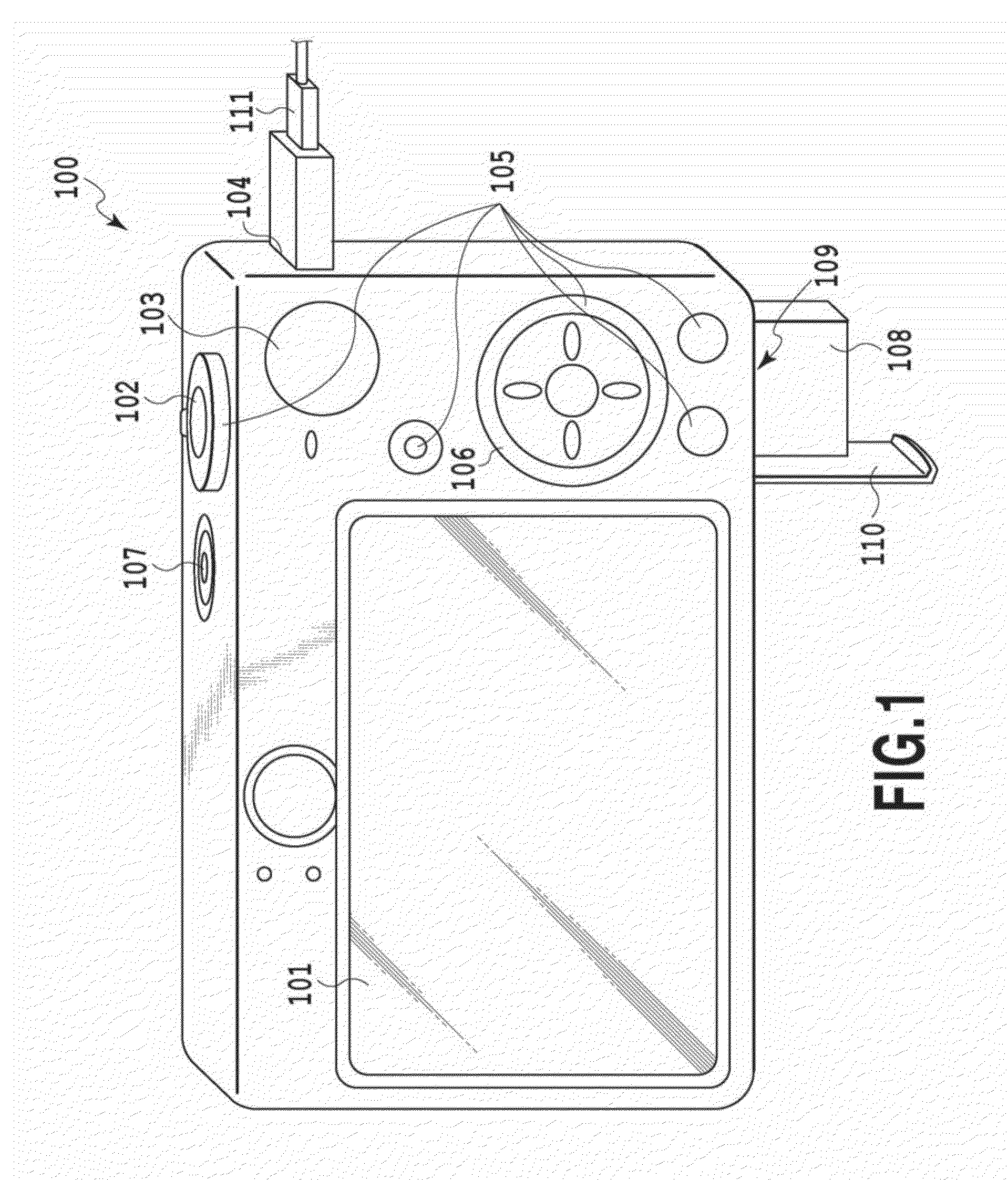
[0054]FIG. 1 is a diagram showing an example of an external appearance of a digital camera.

[0055]In a display unit 101, for example, a liquid crystal display is used and images and various kinds of information are displayed. The display unit 101 has a touch screen function and is capable of detecting a touch on the display unit 101. For example, a touch panel is configured so that the transmittance of light does not affect the display of the display unit 101 and the touch panel is attached to an upper layer of the display surface of the display unit 101. Then, the input coordinates on the touch panel and the display coordinates on the display unit 101 are associated with each other. Due to this, a GUI with which it seems possible for a user to directly operate a screen displayed on the display unit 101 can be configured.

[00...

second embodiment

[0123]Next, an aspect is explained as a second embodiment, in which the image processing apparatus according to the present invention is applied to an information processing apparatus that handles light field data. Explanation of the parts common to those of the first embodiment is simplified or omitted and here, different points are explained mainly.

[0124]First, light field data is explained.

[0125]Light field data (light ray information) is data recording the quantity of light for a light ray path. Specifically, in the data, for a light ray passing through coordinates on two parallel planes (coordinates (u, v) on a first plane and coordinates (x, y) on a second plane), a quantity of light L of the light ray is expressed by L (u, v, x, y) as a function of u, v, x, and y. In contrast to this, a two-dimensional image is expressed by the quantity of light of a light ray at the coordinates (x, y) on the single plane. For example, that which records the quantity of light at the coordinat...

third embodiment

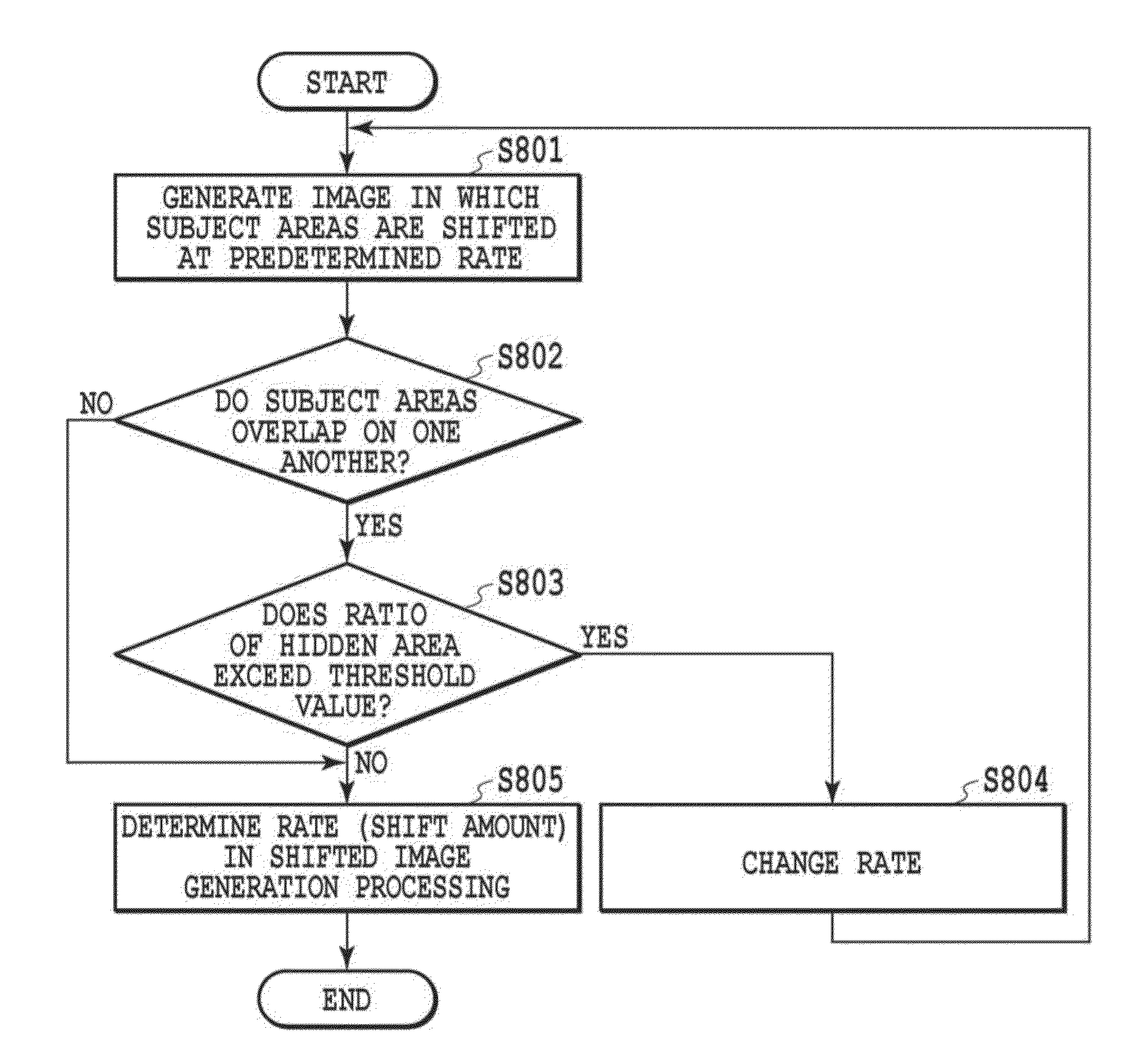
[0156]In the first and second embodiments, it is made possible to intuitively grasp the range in which refocus can be performed by the image (shifted image) in which the position of each subject area is shifted in accordance with the distance of each subject area and which is close to the actual image. In a third and subsequent embodiments, an aspect is explained in which it is made possible to intuitively grasp the range in which refocus can be performed using an image in which the coordinates (arrangement) of each subject area are changed in accordance with the distance of each subject area.

[0157]FIG. 15 is a block diagram showing an internal configuration of a camera array image capturing apparatus (also referred to simply as a “camera array”, as known as a camera array system, multiple lens camera, and the like) according to the present embodiment. An image capturing unit 1500 acquires image data (digital data) by receiving light information of a subject by an image sensing elem...


PUM


Abstract

Conventionally, on a subject in which range, refocus can be performed at the time of image capturing or at the time of editing an image is not specified clearly, and therefore, it is difficult for a user to capture an image or to edit an image in a manner the user intends. An image processing apparatus has an acquisition unit configured to acquire an image including a plurality of subject areas and distance information corresponding to the plurality of subject areas and a generation unit configured to generate a shifted image in which positions of the plurality of subject areas are shifted in the image based on the distance information.

Description

BACKGROUND OF THE INVENTION[0001]1. Field of the Invention[0002]The present invention relates to an image processing apparatus, an image capturing apparatus, an image processing method, and a storage medium for obtaining information on focus control of a subject.[0003]2. Description of the Related Art[0004]As an image capturing apparatus, such as a digital camera, there is known an apparatus that makes focus adjustment of a subject included in a captured image by a user specifying the subject by a touch panel operation etc. (for example, Japanese Patent Laid-Open No. 2011-39457).[0005]Further, the technique is also proposed, which makes it possible for a user to easily grasp an object in focus the image of which is to be captured (subject) by displaying a map image for indicating a depth position representing a position of the object the image of which is to be captured in the depth direction and a focus position representing the position of focus (for example, Japanese Patent Laid-...

Claims


Application Information

Patent Timeline
IPC IPC(8): H04N5/272H04N5/14H04N5/265H04N5/232H04N5/262
CPCH04N5/142H04N5/23212H04N5/23293H04N5/272H04N5/2628H04N5/265H04N5/2624H04N23/959H04N23/80H04N23/632H04N23/635H04N2013/0081G01S17/08H04N23/951H04N23/62
Inventor WATANABE, KAZUHIROSAKATA, OSAMUTAKATANI, KEITAKAKU, WATARUTSUTSUMI, SHOHEI
Owner CANON KK
Why Eureka
Try Eureka