Display apparatus

Active Publication Date: 2014-09-11
TAN CIAN TECH CO LTD
View PDF3 Cites 6 Cited by
  • Summary
  • Abstract
  • Description
  • Claims
  • Application Information

AI Technical Summary

Benefits of technology

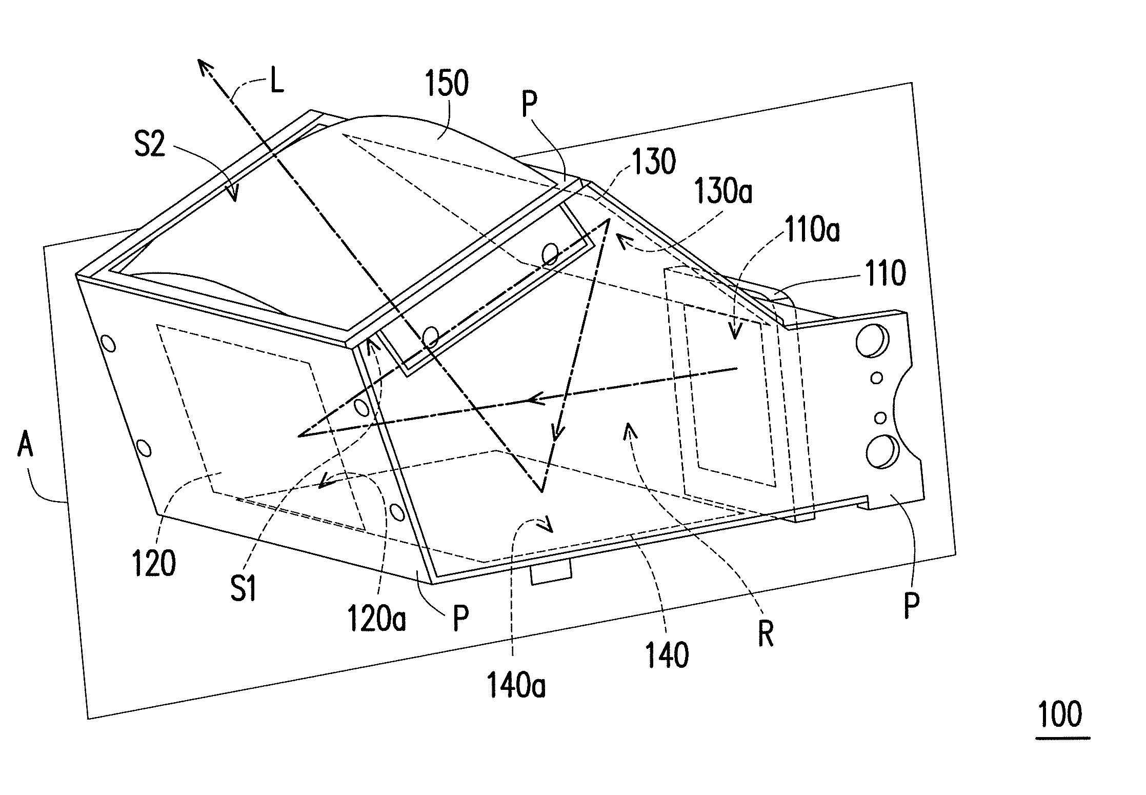
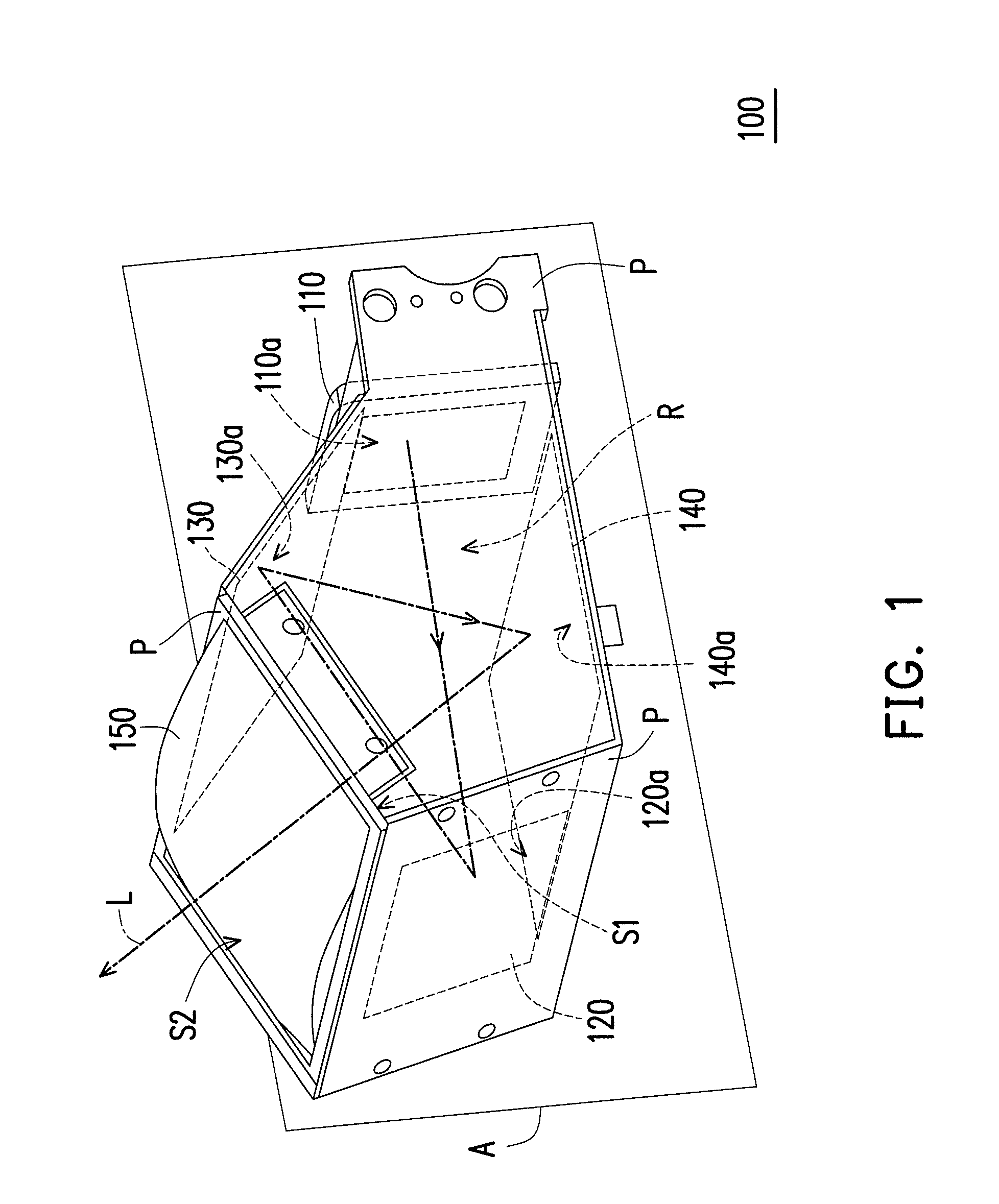
The invention provides a display apparatus that can make images appear farther away and have better quality. This can be used in transportation to make it safer and more comfortable for users. The display unit emits image beams that are reflected by multiple reflectors and sent to a lens unit to create an image. This makes the user's eye distance from the display surface longer, increasing the image distance. This allows users to pay attention to the road conditions and the display at the same time, making the driving safer.

Problems solved by technology

However, traffic safety concerns are likely to be caused when a driver bows to look at the display apparatus installed on the dashboard.
Now, if the attention of the user is unable to continuously focus at road conditions at the distance ahead of the windshield, then it may easily lead to traffic accidents.
Moreover, in the conventional technology, the display apparatus, due to an internal optical configuration thereof, causes the displayed image to be prone to distortion and causes the displayed image unclear to be seen; and therefore, according to the above, how to develop a display apparatus not easily leading to the traffic accidents and enabling the imaging of the display apparatus to have a favorable quality is, in fact, one of the goals for those skilled in the art.

Method used


Image

  • Display apparatus
  • Display apparatus
  • Display apparatus

Examples


Embodiment Construction

[0026]In the following detailed description of the preferred embodiments, reference is made to the accompanying drawings which form a part hereof, and in which are shown by way of illustration specific embodiments in which the invention may be practiced. In this regard, directional terminology, such as “top,”“bottom,”“front,”“back,” etc., is used with reference to the orientation of the Figure(s) being described. The components of the invention can be positioned in a number of different orientations. As such, the directional terminology is used for purposes of illustration and is in no way limiting. On the other hand, the drawings are only schematic and the sizes of components may be exaggerated for clarity. It is to be understood that other embodiments may be utilized and structural changes may be made without departing from the scope of the invention. Also, it is to be understood that the phraseology and terminology used herein are for the purpose of description and should not be ...


PUM


Abstract

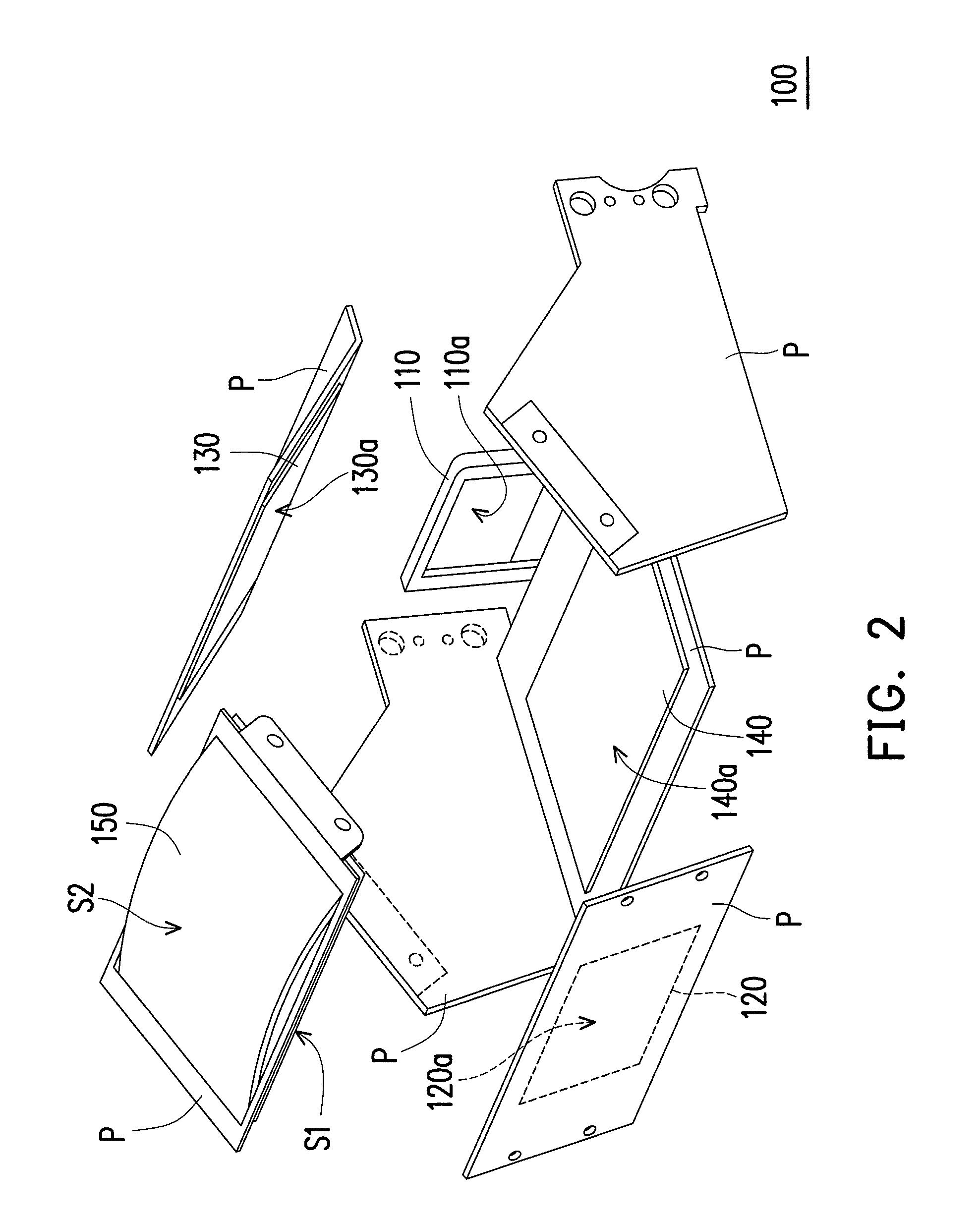
A display apparatus including a display unit, a first reflector, a second reflector, a third reflector and a lens unit is provided. The display unit emits an image beam. The first reflector is disposed on a transmission path of the image beam. The second reflector is disposed on the transmission path of the image beam from the first reflector. The third reflector is disposed on the transmission path of the image beam from the second reflector. The lens unit is disposed on the transmission path of the image beam from the third reflector. The image beam emitted from the display unit passes through a space defined between the second reflector and the third reflector and is transmitted to the first reflector. Afterward, the image beam is sequentially reflected by the first reflector, the second reflector and the third reflector, and then passes through the lens unit.

Description

CROSS-REFERENCE TO RELATED APPLICATION[0001]This application claims the priority benefit of Taiwan application serial no. 102204218, filed on Mar. 7, 2013. The entirety of the above-mentioned patent application is hereby incorporated by reference herein and made a part of this specification.BACKGROUND OF THE INVENTION[0002]1. Field of the Invention[0003]The invention relates to a display apparatus, and more particularly, to a display apparatus having a favorable image quality.[0004]2. Description of Related Art[0005]With yearly rising demands of electronic components used in transportation means, various display apparatuses used in the transportation means have been successively developed. A traditional display apparatus is commonly installed on a dashboard of a vehicle. However, traffic safety concerns are likely to be caused when a driver bows to look at the display apparatus installed on the dashboard. Therefore, a display apparatus capable of projecting an image onto a windshiel...

Claims


Application Information

Patent Timeline
IPC IPC(8): G02B27/01
CPCG02B27/0101G02B5/30
Inventor CHUANG, FU-MINGYU, CHIH-CHIEHWU, CHIH-MENG
Owner TAN CIAN TECH CO LTD
Why Eureka
Try Eureka