Shearing Paddles in a Drum Mixer for Low Slump Concrete

a technology of concrete mixer and shearing paddle, which is applied in clay preparation apparatus, transportation and packaging, chemistry apparatus and processes, etc., can solve the problems of difficult breaking up of unmixed materials' pockets, and achieve the effect of easy breaking up

Active Publication Date: 2014-09-11
STEPHENS MFG CORP
View PDF3 Cites 3 Cited by
  • Summary
  • Abstract
  • Description
  • Claims
  • Application Information

AI Technical Summary

Benefits of technology

[0018]In a preferred embodiment, the teeth and the shearing apertures are both commonly located on intermediate ones of the mixing paddles in the batch mixer. The gaps between adjacent teeth and the shearing apertures encourage the flow of high slump concrete materials therethrough such that larger pockets of material interact with the edges of the teeth and the edges of the apertures to be more readily broken up.
[0020]More preferably, the inclination of the paddles is near to or slightly less than 20 degrees from the longitudinal direction, or in even further embodiments, the paddles may be substantially closer to 0 degrees. By providing a shallow angle on the paddles relative to the longitudinal axis, the concrete materials are less likely to slide longitudinally off of the opposing ends of the paddles.
[0021]The longitudinal sliding of the concrete materials resulting from a steep inclination on the paddles is desirable for ensuring the paddles remain substantially self-cleaning when mixing low slump concrete. However when mixing highly fluid, high slump concrete a shallow inclination of the paddles, for example 10 degrees from the longitudinal axis of the drum, encourages more concrete material to be forced over the toothed outer edge or through the shearing apertures in the paddle surface, thus increasing the opportunity for pockets of unmixed material to be more readily broken up.

Problems solved by technology

These pockets of unmixed material are difficult to break up due to the high fluidity of the mixture and due to the design of the paddles which are intended to be substantially self-cleaning with smooth edges, smooth surfaces, and sharp inclinations relative to the longitudinal axis of the mixer as noted above with regard to reversing drum mixers for example.

Method used


Image

  • Shearing Paddles in a Drum Mixer for Low Slump Concrete
  • Shearing Paddles in a Drum Mixer for Low Slump Concrete
  • Shearing Paddles in a Drum Mixer for Low Slump Concrete

Examples


Embodiment Construction

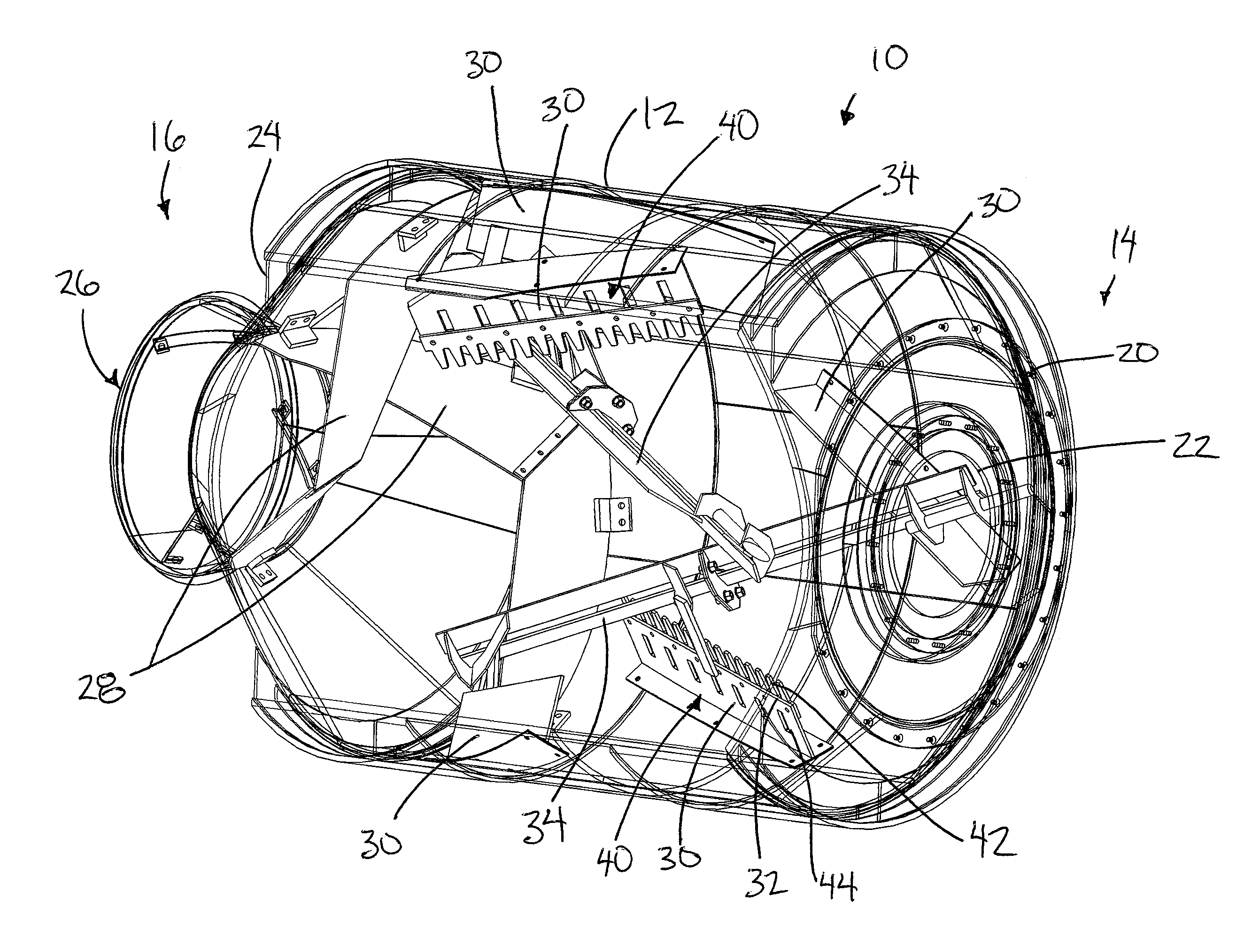
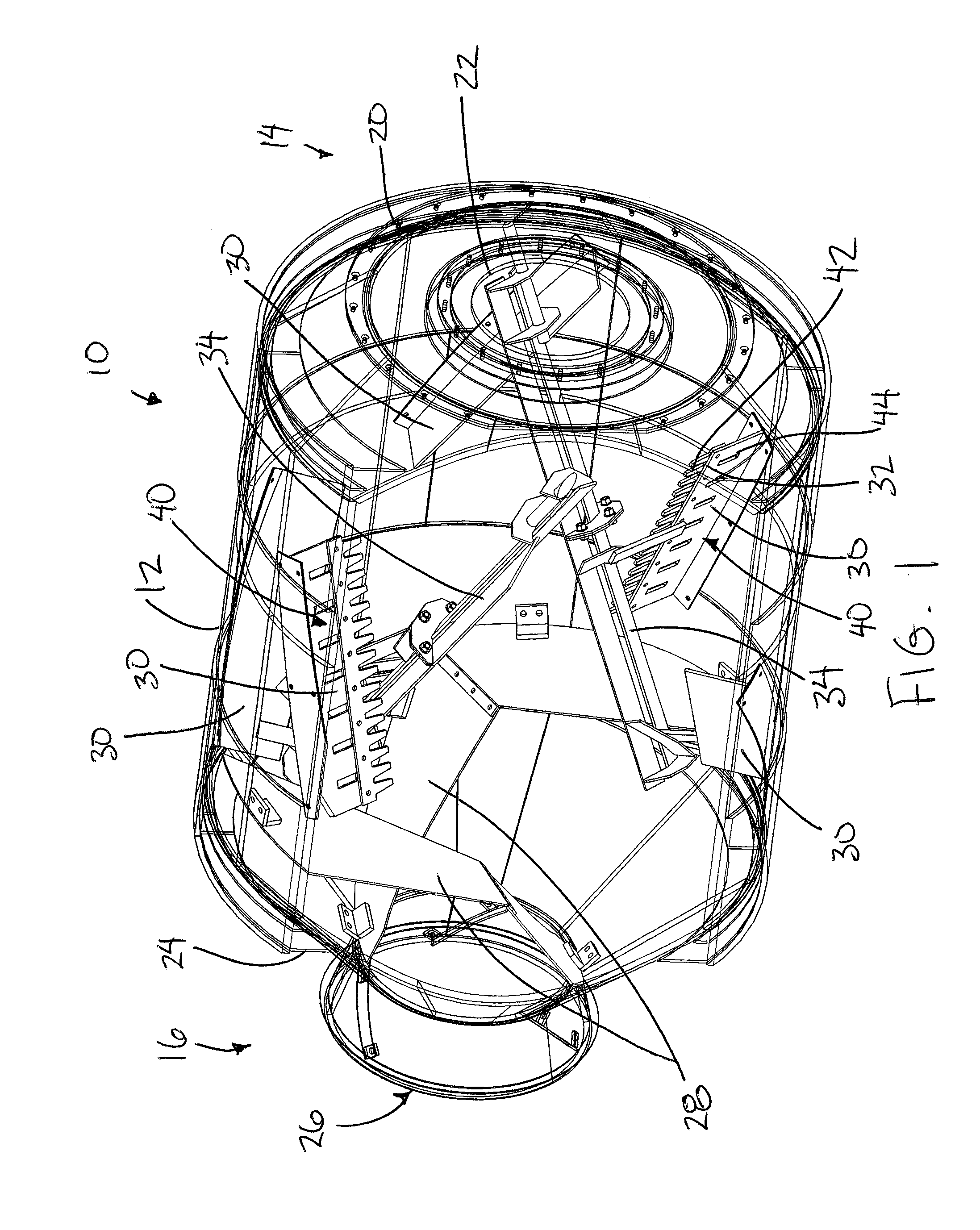
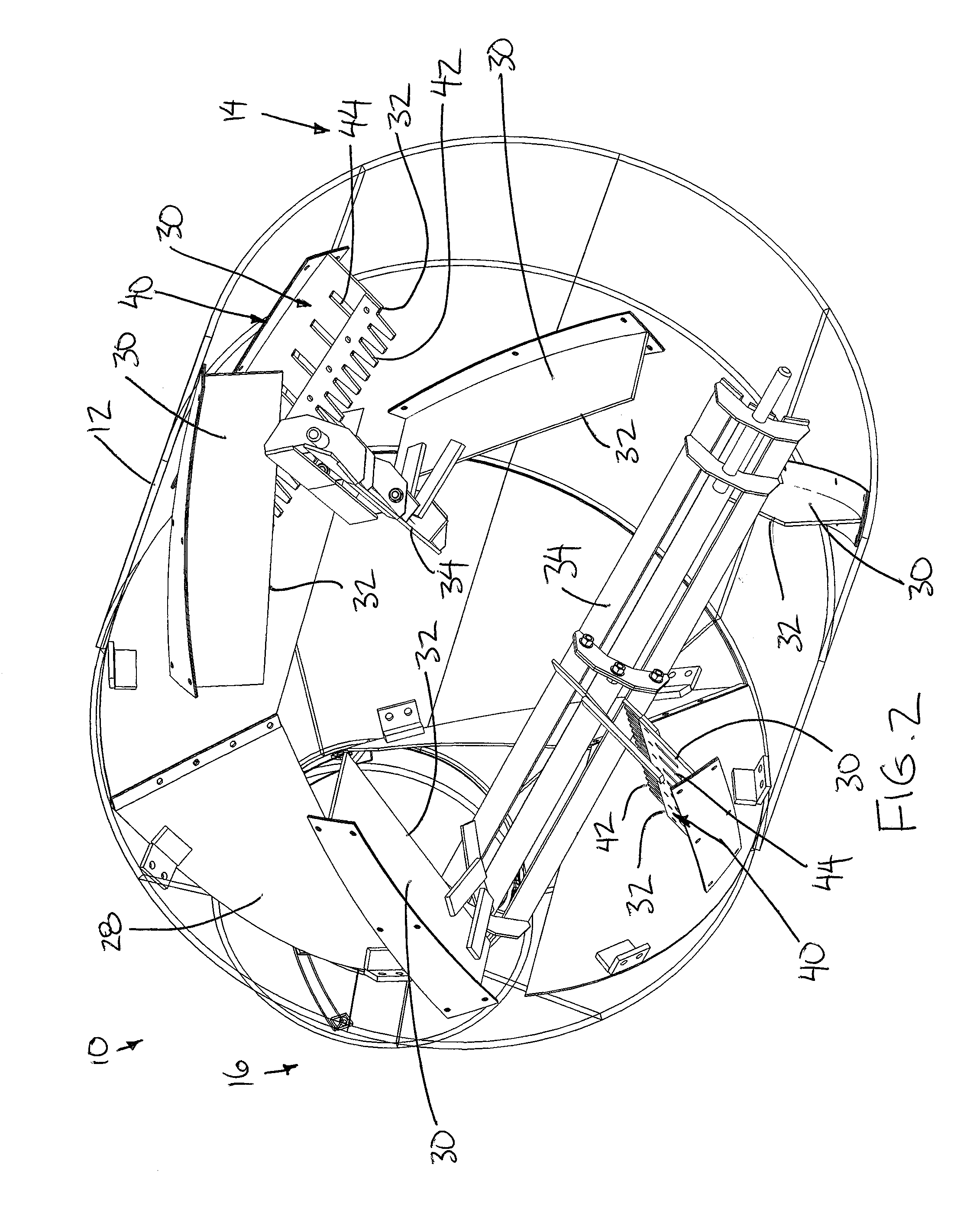
[0038]Referring to the accompanying figures, there is illustrated a batch concrete drum mixer generally indicated by reference numeral 10. The mixer 10 of the illustrated embodiment is a reversing drum mixer for mixing concrete materials into a mixed concrete therein.

[0039]The mixer 10 generally includes a mixer drum 12 having a cylindrical peripheral wall which surrounds a hollow interior of the drum. The peripheral wall extends generally horizontally in the longitudinal direction between an inlet end 14 and an opposing outlet end 16 of the drum.

[0040]The drum is supported on a suitable frame for rotation about a longitudinal axis of the drum. A drive engages the drum to operate the drum either in a mixing mode in which the drum is rotated about the longitudinal axis in a first mixing direction and a discharging mode in which the drum is rotated about the longitudinal axis in an opposing second discharge direction opposite to the mixing direction.

[0041]The drum further includes a f...


PUM

PropertyMeasurementUnit
angleaaaaaaaaaa
radial dimensionaaaaaaaaaa
widthaaaaaaaaaa

Abstract

A batch mixer for mixing concrete materials into a mixed concrete includes a mixing drum having a plurality of paddles fixed to the drum for rotation with the mixing drum about the longitudinal axis of the mixing drum. The paddles include mixing paddles oriented to urge the concrete materials away from the outlet opening at the second end of the drum when the mixing drum is rotated in the mixing direction, and at least one shearing paddle which is oriented at less than 25 degrees from the longitudinal direction of the mixing drum. The shearing paddles has a main body portion interrupted by shearing apertures through which concrete material are directed and an inner edge which is discontinuous and interrupted by longitudinally spaced teeth.

Description

FIELD OF THE INVENTION[0001]The present invention relates to an improved paddle configuration for use in a drum concrete mixer, and more particularly the present invention relates to shearing paddles which are particularly suited for mixing high slump concrete.BACKGROUND[0002]Concrete is commonly mixed in batches in a drum batch mixer, including tilting and non-tilting drum mixers.[0003]One typical configuration of a non-tilting reversing drum mixer includes a horizontally oriented cylindrical drum having an inlet opening at a first end for charging the mixer with concrete materials to be mixed, an outlet opening at an opposing second end for discharging mixed concrete from the drum, and a plurality of mixing paddles supported in the drum to extend generally radially inwardly from the cylindrical wall of the drum for mixing concrete as the drum is rotated. The mixing paddles are oriented to urge the concrete materials towards the inlet opening when the mixing drum is rotated in a fi...

Claims


Application Information

Patent Timeline
Patent Type & Authority Applications(United States)
IPC IPC(8): B28C5/20B01F29/63
CPCB28C5/2063B28C5/2054B01F29/63
Inventor WALLGREN, MARK E.
Owner STEPHENS MFG CORP
Why Eureka
Try Eureka