Gear geometry with fluid reservoir and fluid paths

a technology of fluid reservoir and fluid path, applied in the direction of mechanical equipment, transportation and packaging, gear details, etc., can solve the problems of operator error, secondary lubrication system itself is prone to failure or other problems

Active Publication Date: 2017-06-13
SIKORSKY AIRCRAFT CORP
View PDF29 Cites 3 Cited by
  • Summary
  • Abstract
  • Description
  • Claims
  • Application Information

AI Technical Summary

Benefits of technology

[0006]According to another aspect of the invention, a gear box to transmit torque from an engine to a driven element is provided. The gear box includes a gear train configured to transmit the torque from the engine to the driven element. The gear train includes a gear and the gear includes a body having an axis of rotation, an axial face oriented transversely with respect to the axis and a radial face oriented transversely with respect to the axial face. The axial face is formed to define a fluid reservoir, and fluid paths defined in the body extend from the fluid reservoir to the radial face and are rotatable about the axis to encourage a flow of fluid from the fluid reservoir, through the holes and to the radial face.

Problems solved by technology

In either case, the secondary lubrication systems are themselves prone to failures or are subject to operator error.

Method used


Image

  • Gear geometry with fluid reservoir and fluid paths
  • Gear geometry with fluid reservoir and fluid paths
  • Gear geometry with fluid reservoir and fluid paths

Examples


Embodiment Construction

[0016]As described below, a secondary lubrication system is provided for a helicopter or other rotary wing aircraft that operates continuously and will continue to operate when the primary system fails. The secondary lubrication system is a passive system that operates without any intervention from sensors or an operator and is thus less prone to failures than other secondary lubrication systems and is not subject to operator error.

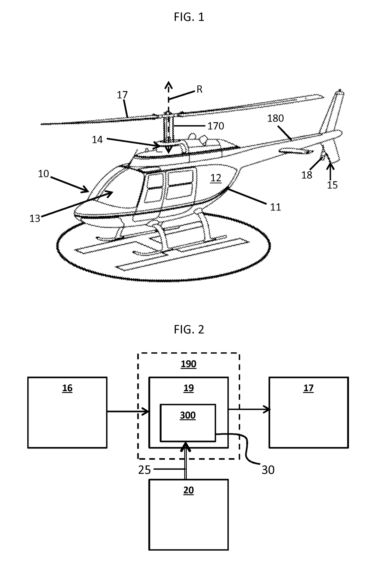
[0017]With reference to FIGS. 1 and 2, a helicopter 10 is provided. The helicopter 10 includes an airframe 11 having a fuselage 12. The fuselage 12 defines a cabin 13 in an interior thereof, a main rotor section 14 and a tail section 15. One or more engines 16 may be operably disposed within the airframe 11, a main rotor 17 may be rotatably supported at the main rotor section 14 and a tail rotor 18 may be rotatably supported at the tail section 15. The main rotor 17 is supported by a main rotor shaft 170 and is disposed to rotate about an axis of rotation...


PUM


Abstract

A helicopter is provided and includes an engine, a rotor, a gear train configured to transmit torque from the engine to the rotor such that the rotor is rotatable about an axis of rotation, a primary lubrication system, which is configured to supply the gear train with a fluid and a secondary lubrication system disposed in a gear of the gear train, including a fluid reservoir, which is configured to receive and store the fluid and to continue to supply the gear train with the fluid following a failure of the primary lubrication system.

Description

BACKGROUND OF THE INVENTION[0001]The subject matter disclosed herein relates to gear geometry with a fluid reservoir and fluid paths.[0002]Helicopters or other rotary wing aircraft typically include an airframe having a fuselage that defines a cabin in an interior thereof, a main rotor section and a tail section. One or more engines may be operably disposed within the airframe, a main rotor may be rotatably supported at the main rotor section and a tail rotor may be rotatably supported at the tail section. The main rotor is supported by a main rotor shaft and is disposed to rotate about an axis of rotation defined along a longitudinal axis of the main rotor shaft. The rotation of the main rotor provides for lift force of the helicopter. The tail rotor is supported by a tail and rotation of the tail rotor provides anti-torque control of the helicopter. Helicopters may further include a gear train operably interposed between the one or more engines and at least the main and tail rotor...

Claims


Application Information

Patent Timeline
Patent Type & Authority Patents(United States)
IPC IPC(8): B64C27/00F16H57/04B64C27/12
CPCF16H57/0442B64C27/12F16H57/045F16H57/0431Y10T74/19991Y10T74/19995
Inventor SAMMATARO, STEPHEN R.PATRY, RYAN
Owner SIKORSKY AIRCRAFT CORP
Why Eureka
Try Eureka