
Channel for capillary flow, biosensor device and method for forming an object having a channel for capillary flow

a biosensor and capillary flow technology, applied in the field of channels, can solve the problems of significant influence of testing results, inconsistent fluid flow provided, and insufficient volumetric flow rate,

Inactive Publication Date: 2010-12-30
ROCHE DIABETES CARE INC
View PDF2 Cites 4 Cited by
  • Summary
  • Abstract
  • Description
  • Claims
  • Application Information

AI Technical Summary

Benefits of technology

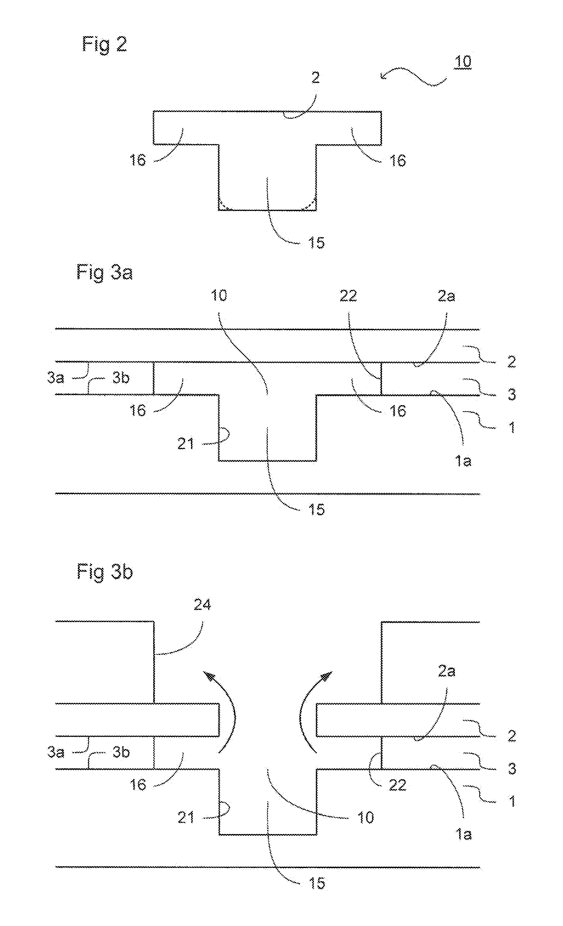
[0008]The extent of capillary action may be determined by a variety of factors. However, the size of a channel or channel portion is an important determining factor. In particular, minimizing the size of the smallest dimension of a channel may increase the capillary action. Accordingly, providing at least one subsidiary channel portion having a relatively small minimum dimension encourages capillary flow across the entire cross-section of the channel. This may be particularly advantageous in the case that a surface of the channel, for example adjacent to the at least one subsidiary channel portion is relatively hydrophobic.
[0010]In an arrangement, the smallest dimension of the cross-section of the main channel portion is between approximately twice as large and ten times as large as the smallest dimension of the cross-section of the at least one subsidiary channel portion. In an arrangement, the at least one subsidiary channel portion may be configured to be between approximately 10 μm and approximately 200 μm across, optionally between approximately 15 μm and approximately 50 μm across, and the main channel may be configured to be between approximately 50 μm and approximately 200 μm across, optionally between approximately 100 μm and approximately 200 μm across. Such arrangements may be particularly beneficial for ensuring consistency of fluid flow through the channel and maximum volumetric flow rate.
[0013]In particular, the main channel portion may be formed by the provision of a groove within a first surface of the first layer of material and the subsidiary channel portions may be formed by the provision of a slot through the layer of adhesive material that is wider than the groove in a direction that is perpendicular to the length of the channel but parallel to a line that lies within the first surface of the first layer of material. Accordingly, when the first and second layers of material are joined together by the layer of adhesive material such that the slot is aligned with the groove, the at least one subsidiary channel portion is formed by the extension of the slot beyond the edges of the groove. It will be appreciated that such an arrangement provides a simple arrangement for forming the desired cross-section of the channel.
[0021]The method of the present invention provides a straightforward means of providing an object having a channel with the desired shape in cross-section, in order to provide a channel with improved fluid flow.
[0024]The layer of adhesive material may be formed with a release layer on one or both surfaces of its primary faces, namely the faces that are to be adhered to the first and second layers of material. In particular, the layer of adhesive material may include a release layer on the surface of the layer of adhesive material that is to adhere to the first surface of the second layer of material. In that case, after the layer of adhesive material has been adhered to the first layer of material, a hydrophilic coating may be applied to the object. In such an arrangement, the hydrophilic coating will be applied to the edges of the slot through the layer of adhesive material and to the surfaces of the first layer of material that are exposed by the slot through the layer of adhesive material. In particular, there may be the surfaces of the groove in the first surface of the first layer of material. However, the release layer may function as a mask, preventing the application of the hydrophilic coating to the object from affecting the adhesion of the layer of adhesive material to the first surface of the second layer of material once the release layer is subsequently removed.

Problems solved by technology

However, a problem of known arrangements of this type is that the fluid flow provided may not be consistent and / or may not have a sufficiently high volumetric flow rate.
This may result in problems in the testing section of a biosensor device.
In particular, if the testing section involves chemical analysis that requires re-suspension of chemicals within the testing section, inadequate or inconsistent fluid flow may result in the testing results being significantly affected.
For example, instead of complete re-suspension of the chemicals, only a gel may form, resulting in improper operation of the testing section.

Method used


Image

  • Channel for capillary flow, biosensor device and method for forming an object having a channel for capillary flow
  • Channel for capillary flow, biosensor device and method for forming an object having a channel for capillary flow
  • Channel for capillary flow, biosensor device and method for forming an object having a channel for capillary flow

Examples


Embodiment Construction

[0032]The following descriptions of the embodiments are merely exemplary in nature and are in no way intended to limit the present invention or its application or uses.

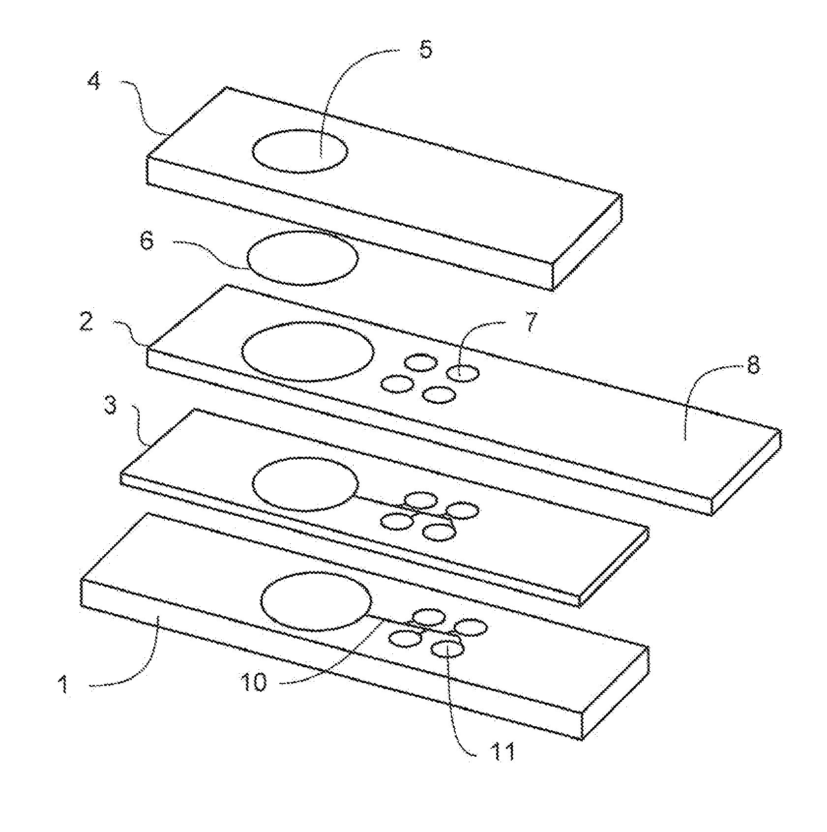
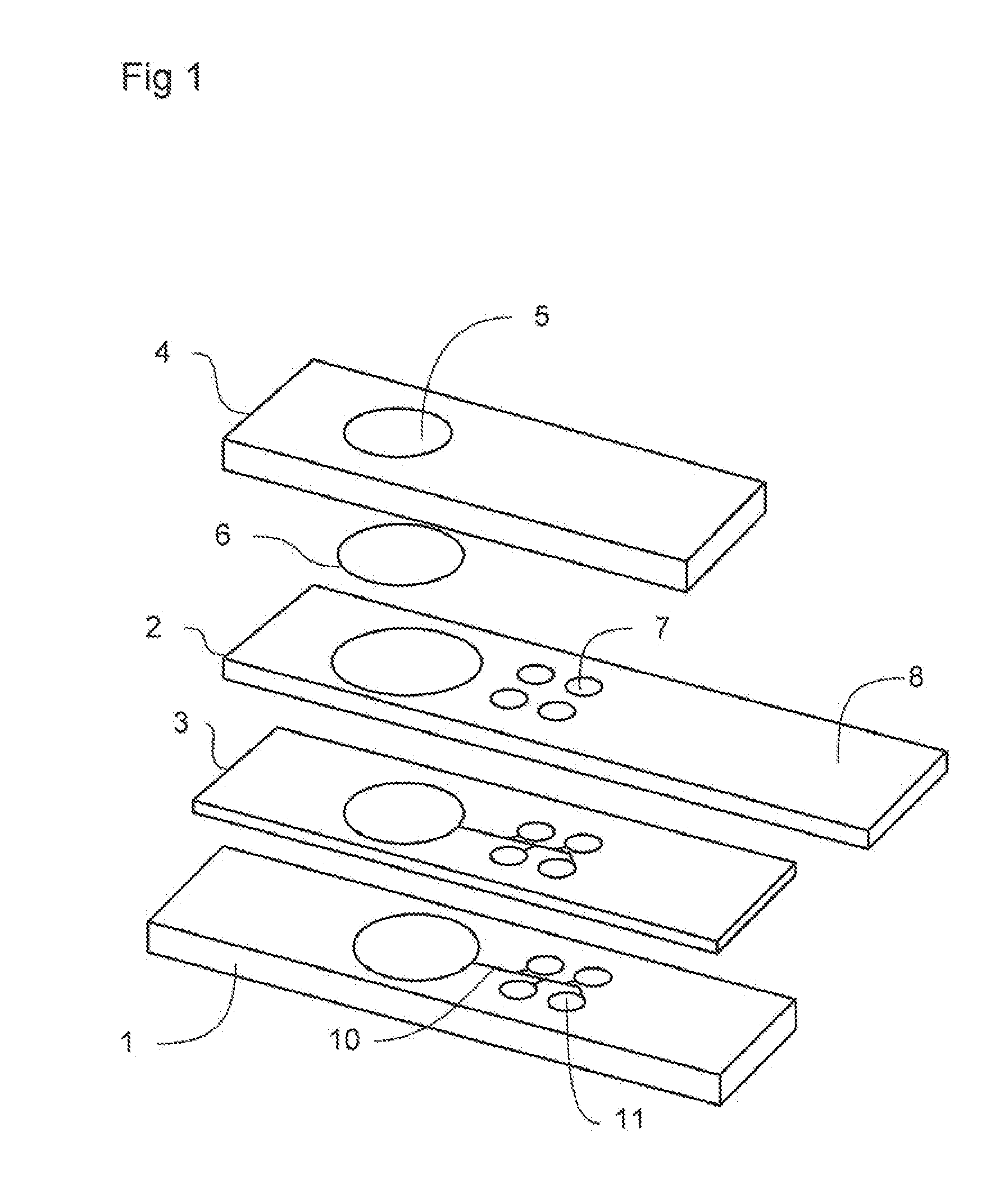
[0033]FIG. 1 depicts an expanded view of an arrangement of a biosensor device that may be used with the present invention.

[0034]As shown, the biosensor device may include a fluid handling layer 1, an analysis layer 2, a layer of adhesive material 3 and a cover layer 4. The cover layer 4 may include an opening 5 that, in conjunction with the fluid handling layer 1, provides a collection area for receiving a fluid sample. A membrane 6 may be provided to filter the fluid sample.

[0035]The analysis layer 2 may include one or more sample analysis, or testing sections 7, at which the fluid is analyzed. It will be appreciated that, depending on the analysis to be performed, any number of testing sections 7 may be provided. As shown, the analysis layer 2 may be provided with an electrode region 8, which may be used to output t...


PUM

PropertyMeasurementUnit
Lengthaaaaaaaaaa
Thicknessaaaaaaaaaa
Flow rateaaaaaaaaaa

Abstract

A channel is provided for conveying fluid by capillary action between a first end of the channel and a second end of the channel, in which the channel is fully enclosed within an object and the cross-section of the channel has a concave shape, encouraging capillary flow.

Description

CLAIM OF PRIORITY[0001]The present application is based on and claims priority to British Application No. GB 0822725.8, filed Dec. 12, 2008, which is hereby incorporated by reference in its entirety.TECHNICAL FIELD OF THE INVENTION[0002]The present invention relates to a channel that is configured to provide capillary flow. In particular, the present invention relates to a channel that is configured to convey fluid by capillary action between a first end of the channel and a second end of the channel. The present invention also relates to a biosensor device incorporating such a channel and to a method of forming an object that includes such a channel.BACKGROUND[0003]In a biosensor device, for example, an arrangement may be provided to convey a fluid to be sampled from a collection area to a testing area in which the sample may be analyzed. It has previously been known to provide a channel or groove that conveys fluid from the collection area to the testing area by capillary action.[...

Claims


Application Information

Patent Timeline
IPC IPC(8): G01N27/26
CPCB01L2300/0887B01L2300/161B01L2400/0406B01L2400/084B81B2201/0214B81B2201/051B01L2300/0825B81B2203/0392B81C1/00119B01L3/50273B01L2300/0636B01L2300/0645B81B2203/0338
Inventor HYLAND, MARKHALLYNCK, SYLVAINSCHOEN, CHRISTIANWAGENER, MICHAEL
Owner ROCHE DIABETES CARE INC
Learn More