Fracturing pump assembly and method thereof

a technology of pump assembly and pump body, which is applied in the direction of piston pump, positive displacement liquid engine, borehole/well accessories, etc., can solve the problem that the pump tends to fatigue rather quickly

Active Publication Date: 2014-09-11
BJ ENERGY SOLUTIONS LLC FORMERLY TES ASSET ACQUISITION LLC
View PDF6 Cites 48 Cited by
  • Summary
  • Abstract
  • Description
  • Claims
  • Application Information

AI Technical Summary

Problems solved by technology

Such pumps tend to fatigue rather quickly because of the extreme pressures and the high cycles per minute rate of operation.

Method used


Image

  • Fracturing pump assembly and method thereof
  • Fracturing pump assembly and method thereof
  • Fracturing pump assembly and method thereof

Examples


Embodiment Construction

[0014]A detailed description of one or more embodiments of the disclosed apparatus and method are presented herein by way of exemplification and not limitation with reference to the Figures.

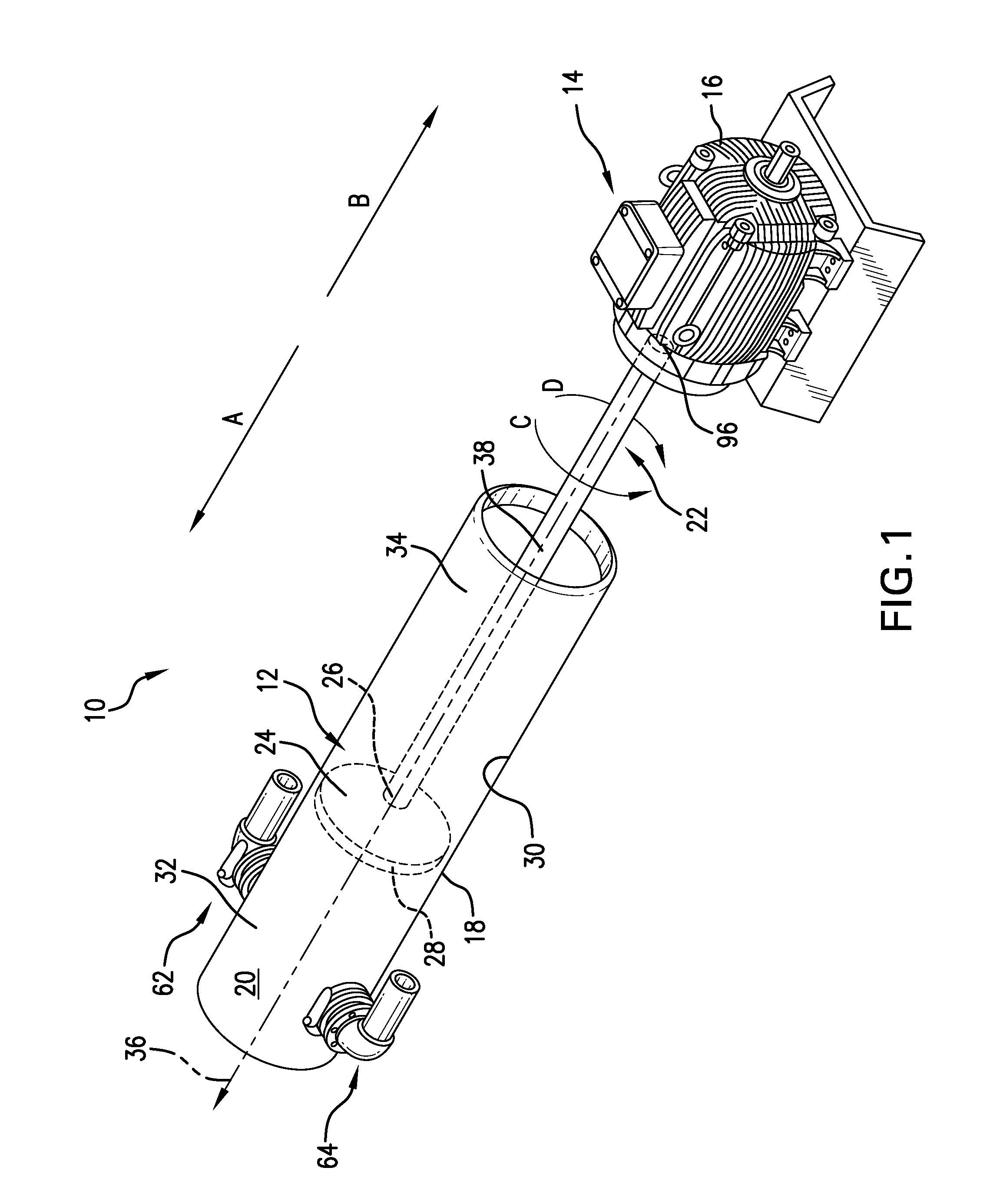
[0015]With reference to FIG. 1, an exemplary embodiment of a fracturing fluid pump assembly 10, alternately termed a fracturing pump assembly or more simply a frac pump, employs an intensifier 12 actuated by a power source 14. In the illustrated embodiment, the power source 14 is an electric motor 16, although other power sources, motors, engines, and prime movers could alternatively be employed to actuate the intensifier 12. Depending on the location of the electric motor 16 with respect to the intensifier 12, the pump assembly 10 further includes any gearing necessary to enable actuation of the intensifier 12 by the electric motor 16. The intensifier 12 includes a long hydraulic cylinder 18 to pump a fluid 20, such as a fracturing fluid including but not limited to a proppant filled slurry, dow...


PUM


Abstract

A fracturing pump assembly includes an intensifier including a hydraulic cylinder, a compression member arranged within the hydraulic cylinder and a rotatable member, wherein the compression member is linearly actuated within the hydraulic cylinder by rotation of the rotatable member.

Description

BACKGROUND[0001]In the drilling and completion industry, the formation of boreholes for the purpose of production or injection of fluid is common The boreholes are used for exploration or extraction of natural resources such as hydrocarbons, oil, gas, water, and alternatively for CO2 sequestration. To increase the production from a borehole, the production zone can be fractured to allow the formation fluids to flow more freely from the formation to the borehole. The fracturing operation includes pumping fluids at high pressure towards the formation to form formation fractures. To retain the fractures in an open condition after fracturing pressure is removed, the fractures must be physically propped open, and therefore the fracturing fluids commonly include solid granular materials, such as sand, generally referred to as proppants. Other components of the fracturing fluids typically include water, gel, or other chemical additives.[0002]To pump the fracturing fluids at the high pressu...

Claims


Application Information

Patent Timeline
Patent Type & Authority Applications(United States)
IPC IPC(8): F15B3/00
CPCF15B3/00F04B17/03F04B9/107F04B23/06F15B15/04E21B43/2607
Inventor BURNETTE, BLAKE
Owner BJ ENERGY SOLUTIONS LLC FORMERLY TES ASSET ACQUISITION LLC
Why Eureka
Try Eureka