Techniques for slicing a 3D model for manufacturing

Active Publication Date: 2014-09-11
AUTODESK INC
View PDF25 Cites 21 Cited by
  • Summary
  • Abstract
  • Description
  • Claims
  • Application Information

AI Technical Summary

Benefits of technology

The patent describes a method for quickly and easily creating 3D models without needing a professional manufacturer. The technique involves using a slicing engine to create a virtual model, which can then be printed onto fabrication material and connected to build the model.

Problems solved by technology

The blueprint typically describes, only at a high level, the structural aspects of the 3D model, but does not provide any further assistance to the designer regarding how to manufacture the physical representation.
Having to resort to a manufacturer in the design phase is typically undesirable for the designer because of two primary factors.
First, production costs of building the physical representation increase when the designer involves the manufacturer.
Second, the time to build the physical representation is dramatically increased if the designer is required to build the physical representation through a manufacturer.

Method used


Image

  • Techniques for slicing a 3D model for manufacturing
  • Techniques for slicing a 3D model for manufacturing
  • Techniques for slicing a 3D model for manufacturing

Examples


Embodiment Construction

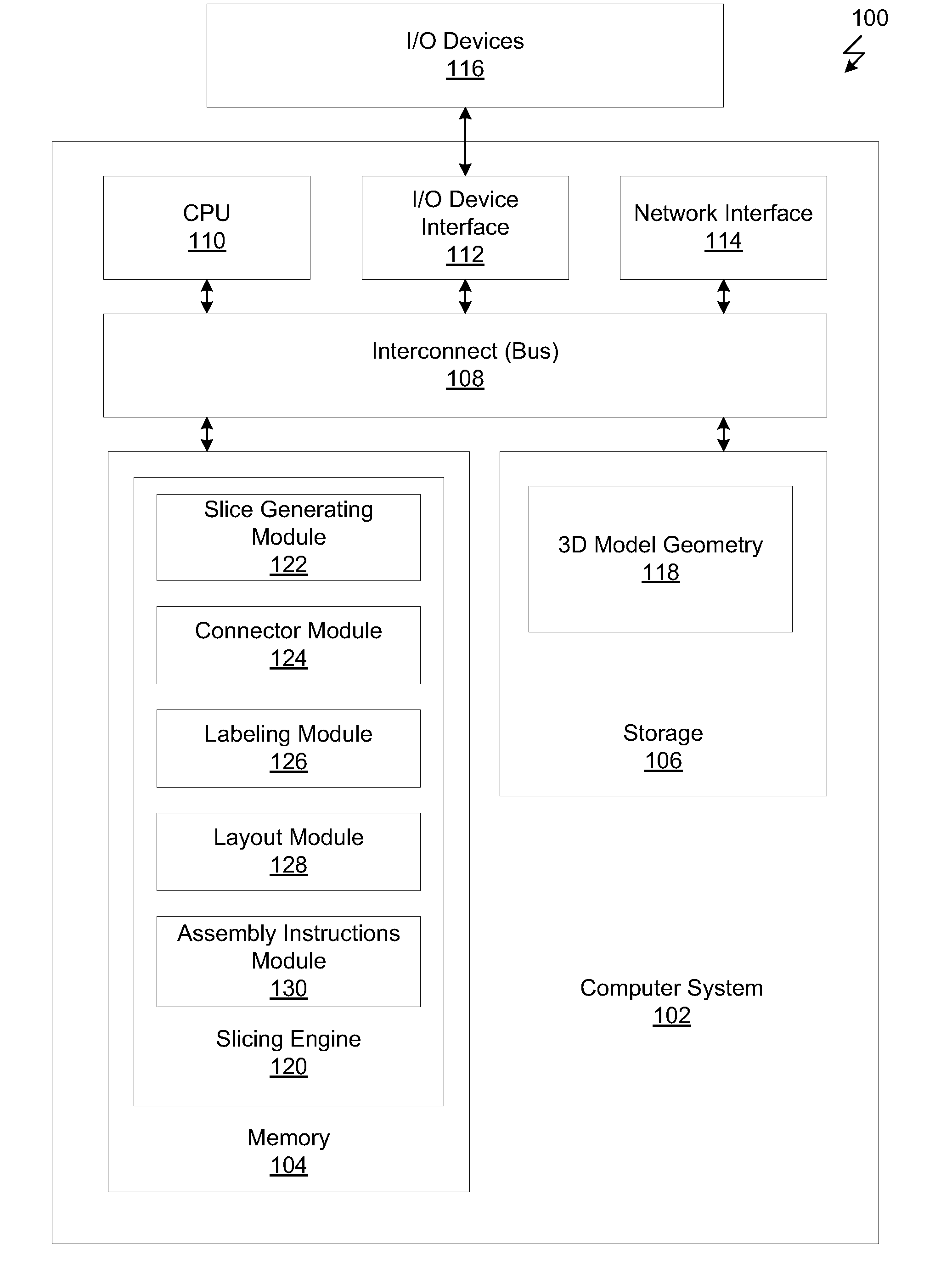
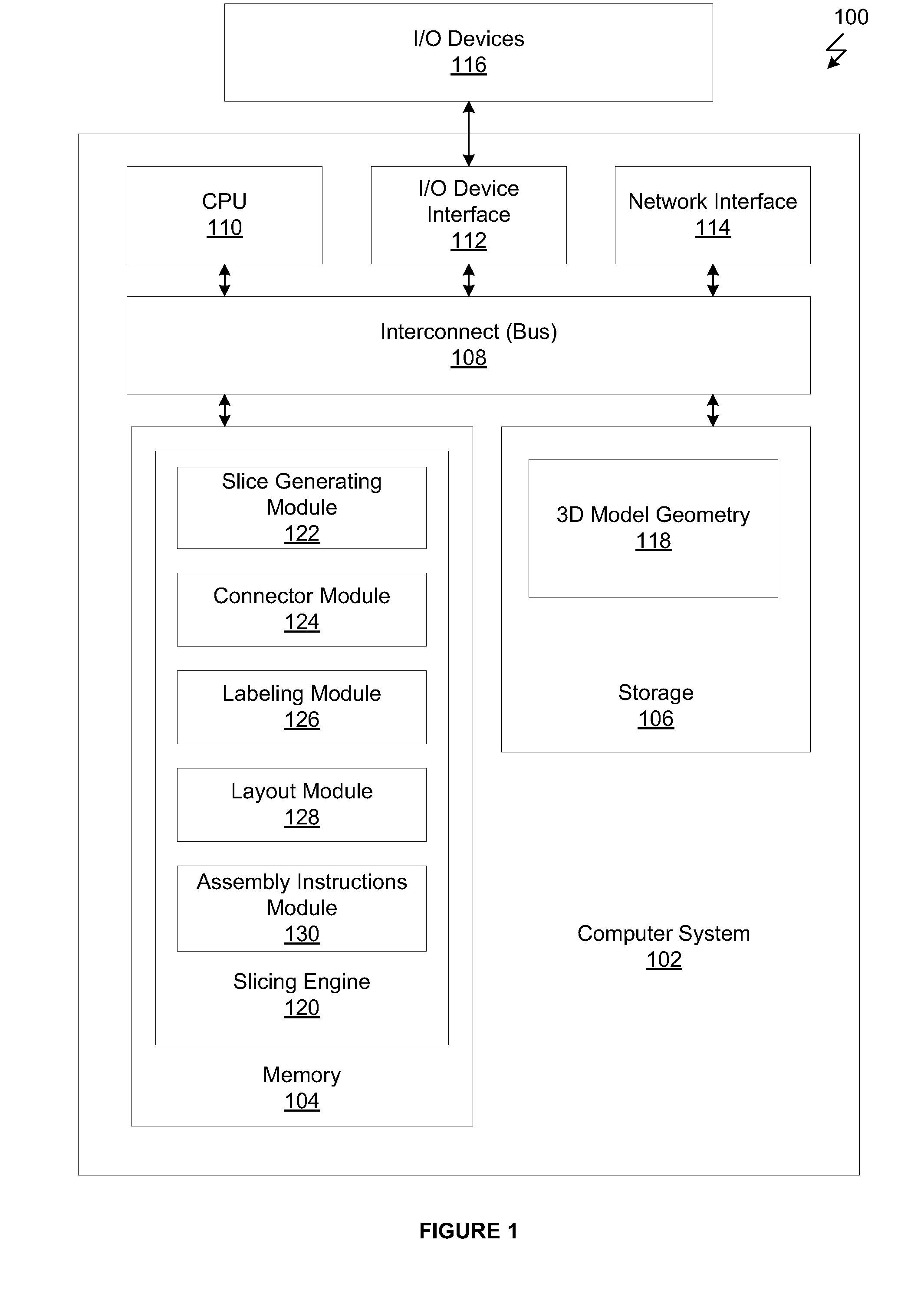
[0027]FIG. 1 illustrates an example system 100 configured to slice a 3D model and prepare the sliced model for manufacturing, according to one embodiment of the invention. As shown, the computing system 100 includes, without limitation, a computer system 102 and input / output (I / O) devices 116. The computer system 102 includes a memory 102, storage 106, a central processing unit (CPU) 110, an I / O device interface 112, a network interface 114 and a bus 108. The I / O device interface 112 interfaces with the I / O devices 116 (e.g., keyboard, display and mouse devices).

[0028]CPU 110 retrieves and executes programming instructions stored in the memory 102. Similarly, CPU 110 stores and retrieves application data residing in the memory 102. The bus 108 transmits programming instructions and application data between the CPU 110, I / O devices interface 112, storage 106, network interface 114 and memory 102. CPU 110 is included to be representative of a single CPU, multiple CPUs, a single CPU ha...


PUM


Abstract

One embodiment of the invention is a slicing engine that generates two or more slices of a virtual 3D model given a slice plane. The slicing engine then determines connection points on each of the slices that indicate how the 3D model is to be reconnected by the user when the 3D model is fabricated. The slicing engine also determines an optimized layout for the various slices of the 3D model on fabrication material for minimal use of the material. The user is then able to “print” the layout on the fabrication material via 3D printers, and connect the various printed slices according to the connection points to build a physical representation of the 3D model.

Description

BACKGROUND OF THE INVENTION[0001]1. Field of the Invention[0002]Embodiments presented in this disclosure generally relate to computer aided design (CAD) and computer aided manufacturing (CAM). More specifically, embodiments presented herein provide techniques for slicing 3D models for manufacturing.[0003]2. Description of the Related Art[0004]CAD / CAM applications provide software modeling tools used to create designs for real-world three-dimensional (3D) objects. For example, a designer may use such a software application to create a 3D model of a constructible toy having a particular shape when inflated. Other examples include 3D computer models of sculpture, furniture, clothing, etc.[0005]Some designers may wish to manufacture a 3D model created in a CAD / CAM application. Typically, to facilitate manufacturing, the CAD / CAM application processes the 3D model to create a blueprint. The designer can then submit the blueprint to a third-party manufacturer for building a physical repres...

Claims


Application Information

Patent Timeline
IPC IPC(8): G05B19/4099
CPCG05B19/4099G05B2219/34103Y02P80/40
Inventor BACHRACH, JOHNATHANGRIFFITH, SAUL
Owner AUTODESK INC
Why Eureka
Try Eureka