Single wall duct flashing panel

a technology of duct flashing and single wall, applied in the field of moisture barrier, can solve the problems of caulking material eventually giving way or not initially caulking properly, substantial damage to insulation, dry wall, flooring and/or carpeting on the interior of the building, etc., to achieve the effect of preventing fluid migration, rigidity and strength

Inactive Publication Date: 2014-09-18
GILLERAN WILLIAM J
View PDF8 Cites 19 Cited by
  • Summary
  • Abstract
  • Description
  • Claims
  • Application Information

AI Technical Summary

Benefits of technology

[0011]According to an aspect of the present invention, there is provided a duct flashing panel configured to provide weatherproofing for large diameter single wall duct, such as heating, ventilation and air conditioning (HVAC) duct, extending through the outside walls of a structure. The duct flashing panel includes a panel body and an elastomeric or plastic seal collar sized and configured to circumferentially engage the exterior surface of the duct to form a substantially fluid-tight seal between the exterior surface of the duct and the collar to prevent fluid migration along the duct. The collar includes an annular bead which provides rigidity and strength to the collar to urge the collar into compressive engagement with the exterior surface of the single wall duct.

Problems solved by technology

If such water enters through the exterior building wall, it can cause substantial damage to insulation, dry wall, wood moldings, flooring and / or carpeting on the interior of the building.
Over time, however, such caulking can eventually crack and break, and when this occurs, water can freely travel along the exterior surface of the pipe or duct and into the interior of the building structure.
Once again, although this approach can work initially, the caulking material may eventually give way or may not initially caulk properly, which may allow water to travel along the pipe or duct exterior and into the structure.

Method used


Image

  • Single wall duct flashing panel
  • Single wall duct flashing panel
  • Single wall duct flashing panel

Examples


Embodiment Construction

[0025]The detailed description set forth below in connection with the appended drawings is intended as a description of the presently preferred embodiments of the invention, and is not intended to represent the only form in which the present devices may be developed or utilized. It is to be understood, however, that the same or equivalent functions may be accomplished by different embodiments that are also intended to be encompassed within the spirit and scope of the invention. It is further understood that the use of relational terms such as first, second, and the like are used solely to distinguish one from another entity without necessarily requiring or implying any actual such relationship or order between such entities.

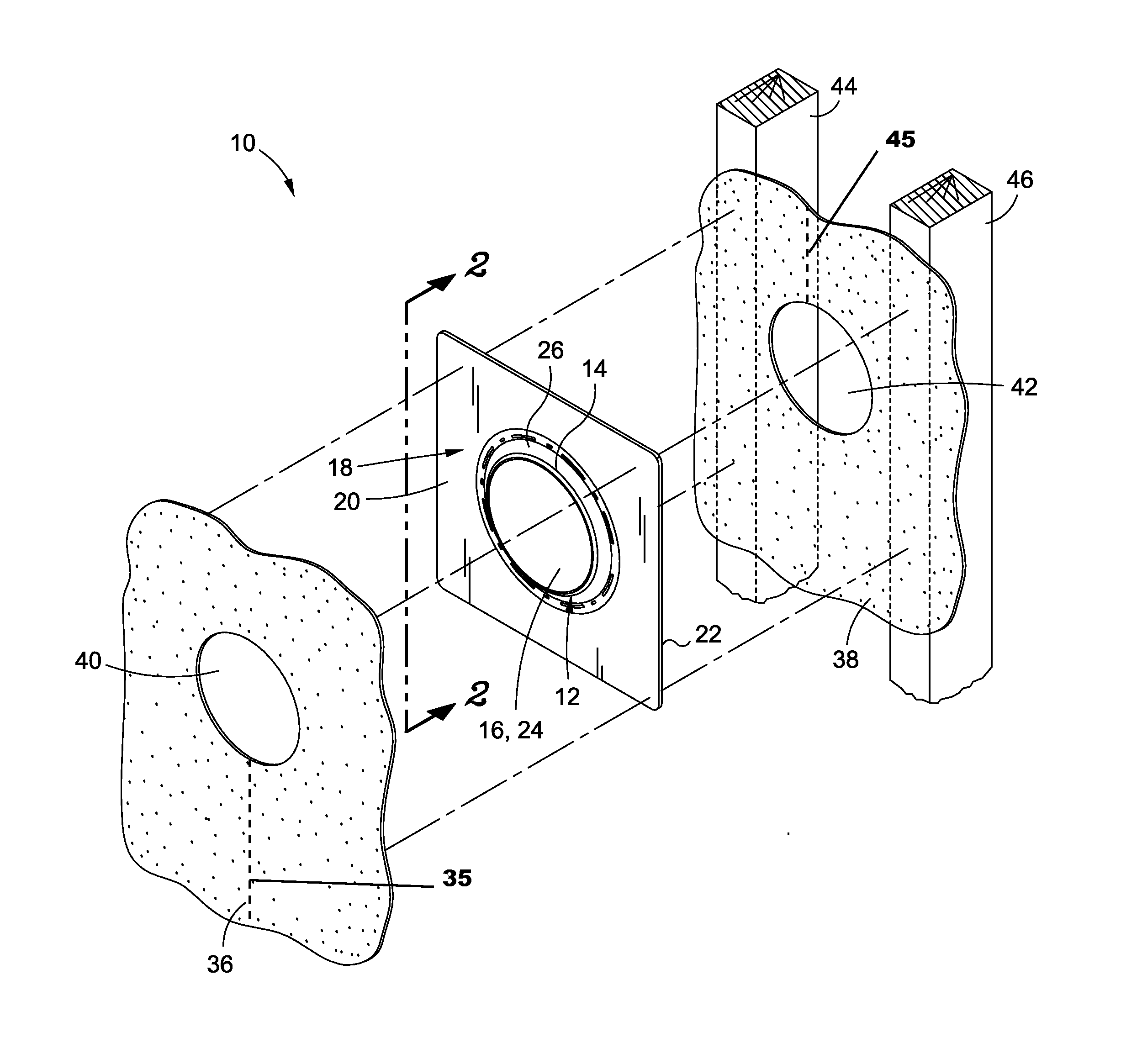
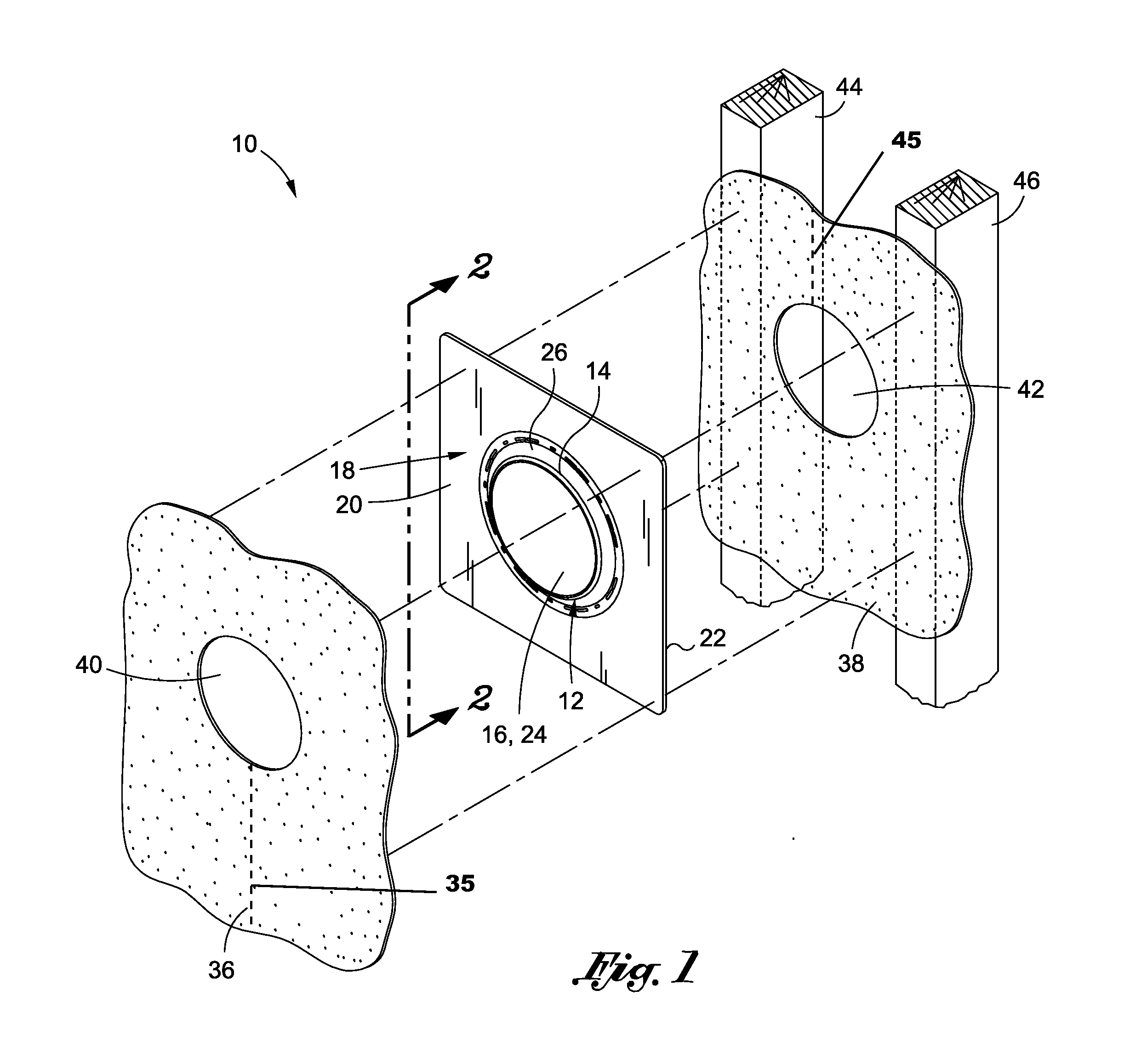
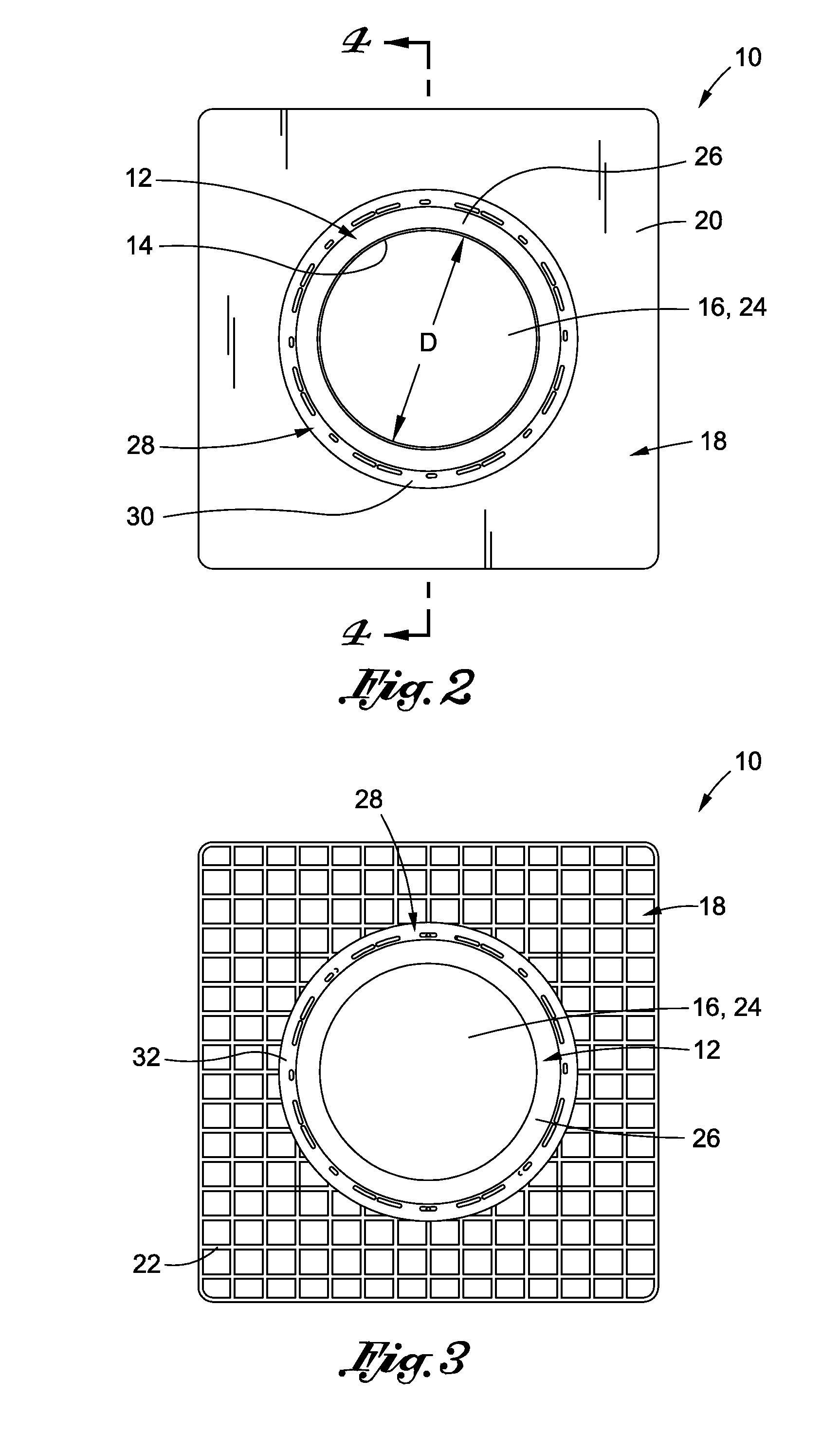
[0026]Referring now to the drawings, wherein the showings are for purposes of illustrating a preferred embodiment of the present invention only, and are not for purposes of limiting the same, there is depicted a duct flashing panel 10 configured for use with larg...


PUM


Abstract

A duct flashing panel configured to provide weatherproofing for single wall ducts extending through the walls of a structure and having a terminal end extending outside of the structure. The duct flashing panel includes a panel body and an elastomeric collar sized and configured to circumferentially engage the exterior surface of the duct to form a fluid-tight seal between the duct and the collar to prevent fluid migration along the exterior of the duct. The collar includes an annular bead which provides rigidity and strength to the collar to urge the collar into compressive engagement with the exterior surface of the duct.

Description

CROSS-REFERENCE TO RELATED APPLICATIONS[0001]This application claims the benefit of U.S. Provisional Application No. 61 / 798,045, filed Mar. 15, 2013, the contents of which are expressly incorporated herein by reference.STATEMENT RE: FEDERALLY SPONSORED RESEARCH / DEVELOPMENT[0002](Not Applicable)BACKGROUND OF THE INVENTION[0003]1. Field of the Invention[0004]The present invention relates generally to a moisture barrier, and more specifically to a moisture barrier flashing panel configured to mitigate moisture migration along the outside surface of a large diameter single wall duct, such as heating, ventilation and air conditioning (HVAC) duct, to provide consistent weatherproofing of the duct.[0005]2. Description of the Related Art[0006]In the construction of homes, commercial buildings, and the like, various utility / plumbing pipes, such as water pipes, gas pipes, drain pipes and heating, ventilation and air conditioning (HVAC) ducts extend through the walls of the building and termin...

Claims


Application Information

Patent Timeline
Patent Type & Authority Applications(United States)
IPC IPC(8): E04B1/66E04B1/64
CPCE04B1/64E04B1/665F16L5/10E04D13/1476E04D13/17
Inventor GILLERAN, WILLIAM J.
Owner GILLERAN WILLIAM J
Why Eureka
Try Eureka