Flow sleeve for a combustion module of a gas turbine

Active Publication Date: 2014-09-18
GENERAL ELECTRIC CO
View PDF8 Cites 25 Cited by
  • Summary
  • Abstract
  • Description
  • Claims
  • Application Information

AI Technical Summary

Problems solved by technology

However, the increase in the temperature of the combustion gases results in an increase of thermal stresses on the combustion liner.
While the flow sleeve assembly is generally effective for cooling the combustion liner, the multiple connections between the various components may leak or develop leaks over time due to tolerance issues and/or due to thermal and/or mechanical cycle fatigue, thereby impacting the overall cooling effecti

Method used


Image

  • Flow sleeve for a combustion module of a gas turbine
  • Flow sleeve for a combustion module of a gas turbine
  • Flow sleeve for a combustion module of a gas turbine

Examples


Embodiment Construction

[0020]Reference will now be made in detail to present embodiments of the invention, one or more examples of which are illustrated in the accompanying drawings. The detailed description uses numerical and letter designations to refer to features in the drawings. Like or similar designations in the drawings and description have been used to refer to like or similar parts of the invention. As used herein, the terms “first”, “second”, and “third” may be used interchangeably to distinguish one component from another and are not intended to signify location or importance of the individual components. The terms “upstream” and “downstream” refer to the relative direction with respect to fluid flow in a fluid pathway. For example, “upstream” refers to the direction from which the fluid flows, and “downstream” refers to the direction to which the fluid flows. The term “radially” refers to the relative direction that is substantially perpendicular to an axial centerline of a particular compone...


PUM


Abstract

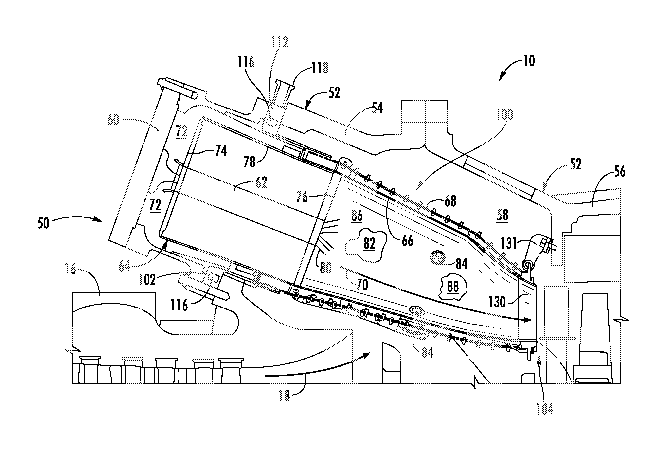
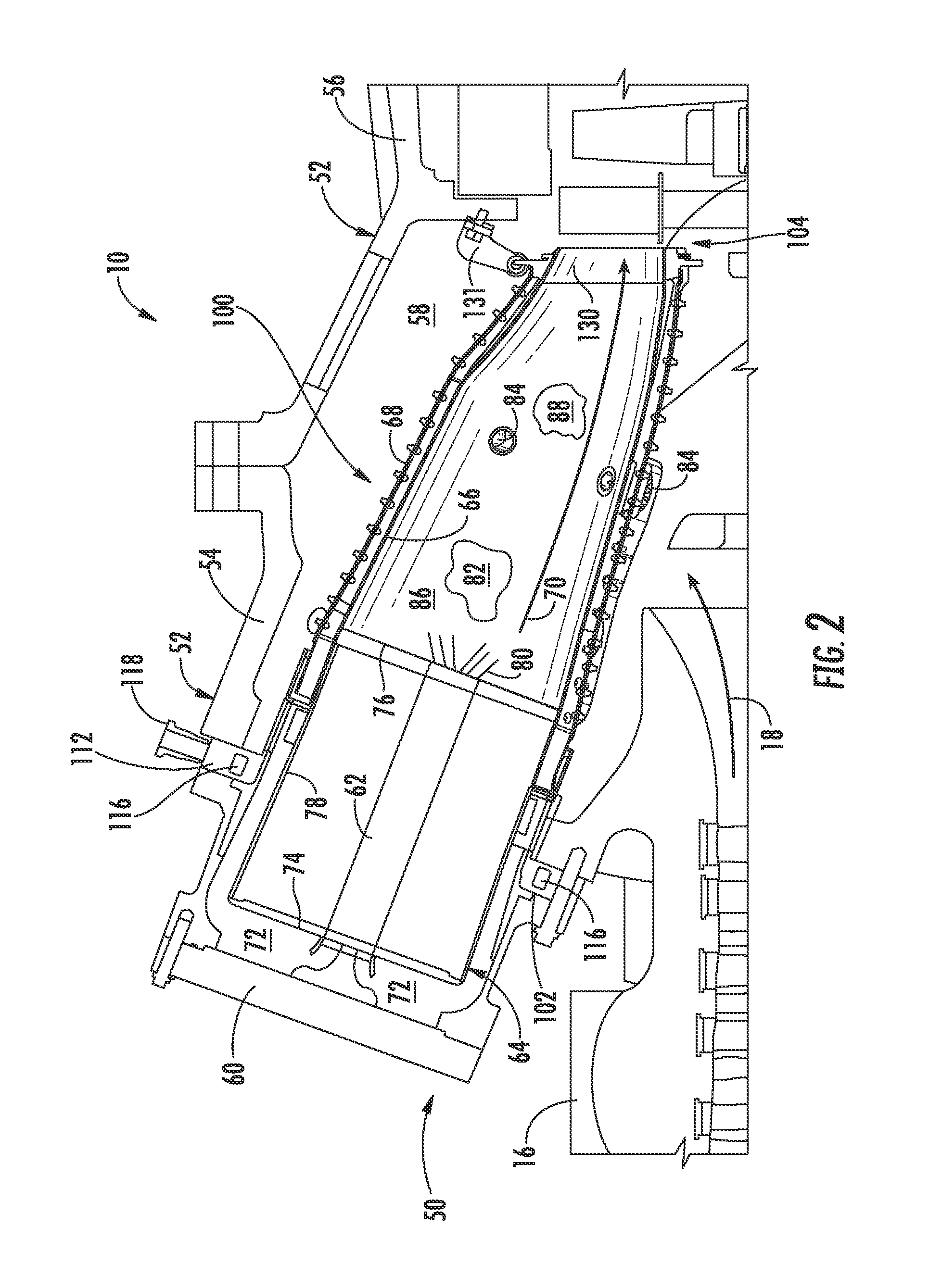
A combustion module for a combustor of a gas turbine includes an annular fuel distribution manifold disposed at an upstream end of the combustion module. The fuel distribution manifold includes an annular support sleeve having an inner surface. The combustion module further includes a fuel injection assembly having an annular combustion liner that extends downstream from the fuel distribution manifold and that terminates at an aft frame, and an annular flow sleeve that circumferentially surrounds the combustion liner. The flow sleeve extends downstream from the fuel distribution manifold and terminates at the aft frame. The flow sleeve extends continuously between the support sleeve and the aft frame. A forward portion of the flow sleeve is positioned concentrically within the support sleeve where the forward portion is slidingly engaged with the inner surface of the support sleeve.

Description

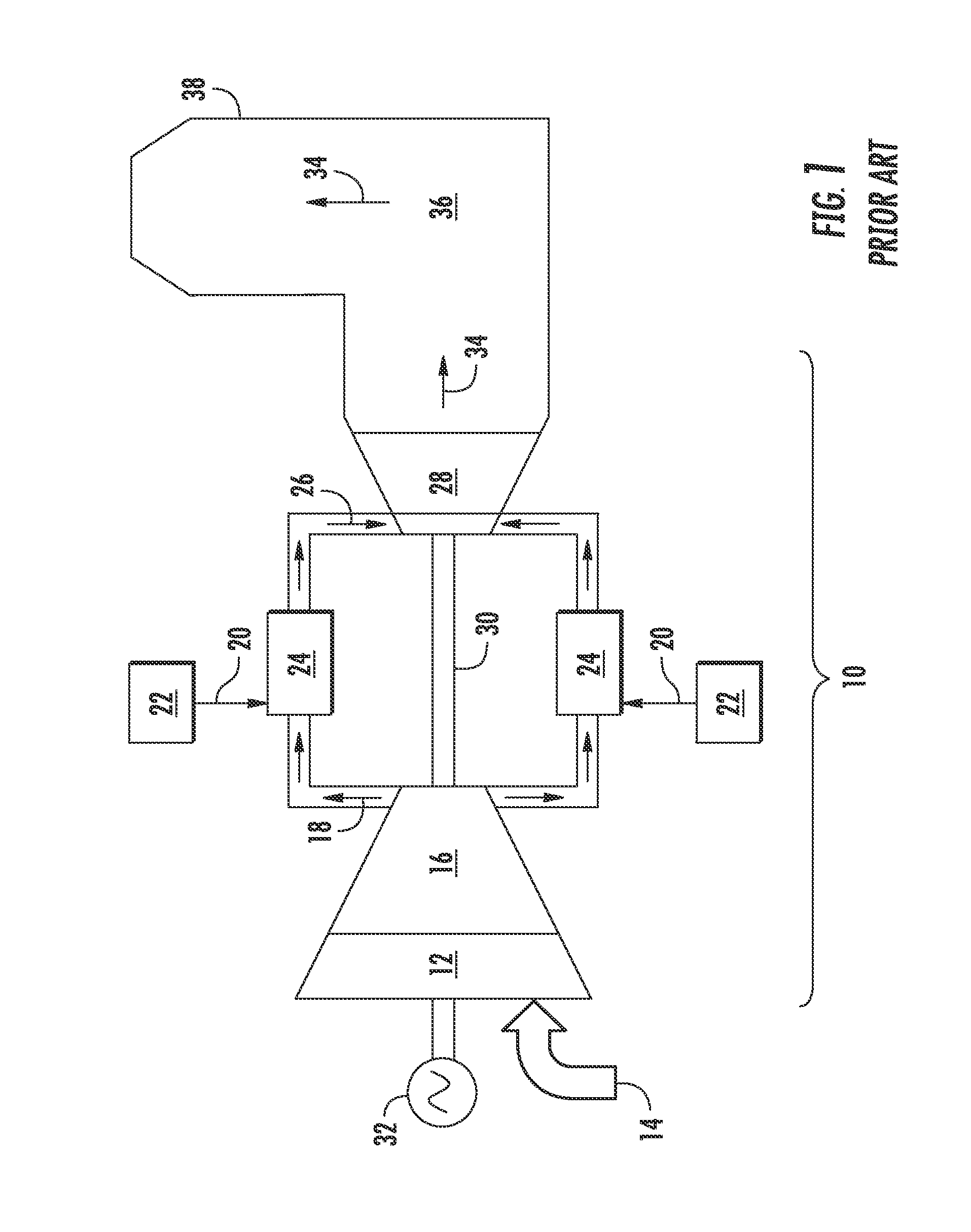
FIELD OF THE INVENTION[0001]The present invention generally involves a combustor for a gas turbine. More specifically, the invention relates to a flow sleeve for a combustion module of the combustor.BACKGROUND OF THE INVENTION[0002]A combustion section of a gas turbine generally includes a plurality of combustors that are arranged in an annular array around an outer casing such as a compressor discharge casing. Pressurized air flows from a compressor to the compressor discharge casing and is routed to each combustor. Fuel from a fuel nozzle is mixed with the pressurized air in each combustor to form a combustible mixture within a primary combustion zone of the combustor. The combustible mixture is burned to produce hot combustion gases having a high pressure and high velocity.[0003]In a typical combustor, the combustion gases are routed towards an inlet of a turbine of the gas turbine through a hot gas path that is at least partially defined by an annular combustion liner and an ann...

Claims


Application Information

Patent Timeline
IPC IPC(8): F23R3/20
CPCF23R3/20F23R3/005F23R3/46F23R3/60F23R2900/00017F23R2900/03043F23R2900/03045F23R3/34F02C7/22
Inventor DICINTIO, RICHARD MARTINMELTON, PATRICK BENEDICTSTOIA, LUCAS JOHNWILLIS, CHRISTOPHER PAULPENTECOST, RONNIE RAY
Owner GENERAL ELECTRIC CO
Why Eureka
Try Eureka