
Shear system of extrusion press

a shear system and extruder technology, applied in the field of shear systems of extruders, can solve the problems of insufficient container seals, poor cutting surface of discards, and insufficient thickness of so as to maintain the sharpness of the shear blade, the die stack tilts, and the thickness of the cutting scraps of discards is uniform.

Active Publication Date: 2014-09-18
UBE MASCH CORP LTD
View PDF4 Cites 9 Cited by
  • Summary
  • Abstract
  • Description
  • Claims
  • Application Information

AI Technical Summary

Benefits of technology

The present invention is designed to prevent tilting of a die stack and ensure a uniform thickness of cutting scraps when discarding. It achieves this by automatically tracking the position of a shear blade across the surface of the die stack, regardless of variations in the thickness or deformation of the shear frame. This results in a constant clearance between the die stack end face and shear blade, maintaining stable sharpness of the shear blade. This prevents blisters, reduces impurities in the extruded product, and increases the yield of the product.

Problems solved by technology

When cutting off the discard, if the clearance between the shear blade and the die end face grows wider, the cut surface of the discard will become poor and cutting burrs will be formed.
When the container and die abut against each other to seal the container at the time of the next extrusion operation, the burrs will be interposed between the container seal surfaces and the container seal will become insufficient.
Further, if there is a ring-shaped port hole for the billet at the container side of the die, the aluminum alloy inside of the port hole will be gouged away at the time of cutting by the shear blade.
The cut end surface will not also be uniform but will have an uneven shape due to being gouged.
Furthermore, the configuration for attaching to the shear slide a guide roller which guides the shear blade and making the shear system as a whole tilt is complicated, so the shear system rose in cost.

Method used


Image

  • Shear system of extrusion press
  • Shear system of extrusion press
  • Shear system of extrusion press

Examples


Embodiment Construction

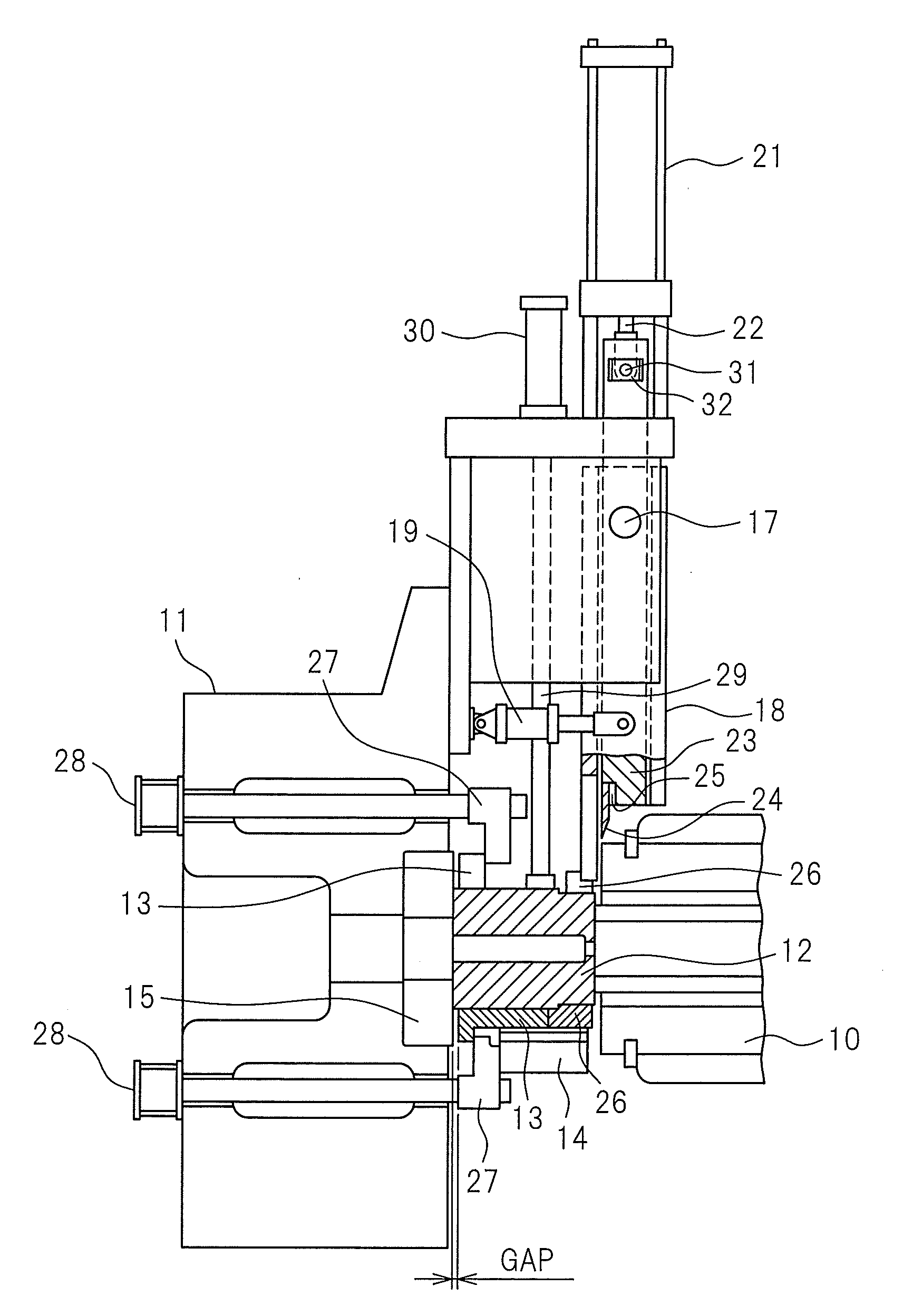
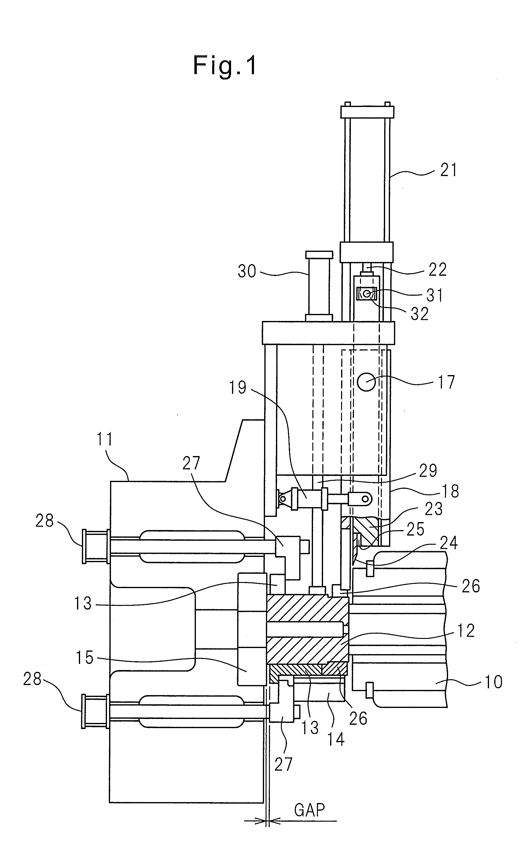
[0019]FIGS. 1 to 4 will be used to explain an embodiment of the present invention. In FIG. 1, reference numeral 11 indicates an end platen, 12 a die stack, 13 a die block, 14 a guide member which guides movement in a horizontal direction which is perpendicular with the paper surface of the figure of the die block 13, and 15 a pressure ring inside the end platen which receives the pushing force from the die stack 12. At the center parts of the pressure ring 15 and the end platen 11, holes are provided through which the product which is extruded from the die stack 12 passes. Note that, the die stack 12 is configured by a not shown plurality of parts.

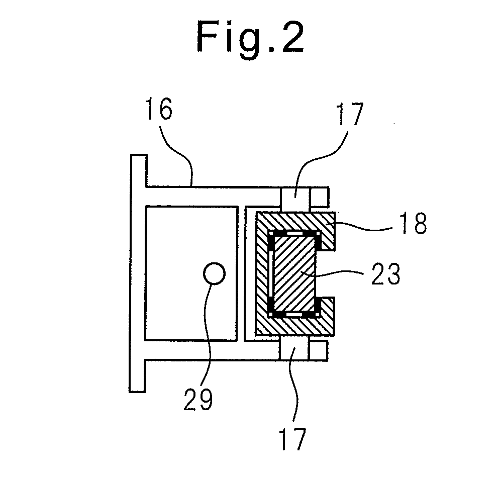
[0020]At an upper container side of the end platen 11 which holds the die stack 12 at its front surface side, a shear frame 16 is attached. At the top end part of the shear frame 16, a shear cylinder 21 for discard cutting-use is attached. At part of the shear frame 16, a shear guide 18 is attached by a shaft 17 to be able to turn in the e...


PUM

PropertyMeasurementUnit
temperatureaaaaaaaaaa
timeaaaaaaaaaa
shapeaaaaaaaaaa

Abstract

A shearing device for an extrusion press is adapted for cutting off from each other an extruded product and a discard which is the residue of a billet, the shearing device being configured so that the configuration thereof is simplified to reduce costs required for maintenance and production and so that the gap between the shear blade and an end surface of a die is automatically adjusted to improve the shearing accuracy, thereby providing a satisfactory cut surface. A shear cylinder (21) is mounted in a downward facing position to a frame (16) provided on the side of an end platen (11) which faces a container (10). A shear guide (18) is mounted to the frame (16) in a tiltable manner, the shear guide (18) having a shear blade (24) which is provided at the lower end thereof and guiding a shear slide (23). A tilt cylinder (19) for the shear guide (18) is mounted to the frame (16), the tilt cylinder (19) being capable of keeping the gap between the front face of a die stack (12) and the shear blade (24) constant by pressing the shear guide (18) against a horseshoe (26). The piston rod (22) of the shear cylinder (21) is mounted to the shear slide (23) so as to be capable of tilting and sliding.

Description

CROSS REFERENCE TO RELATED APPLICATION[0001]The present invention claims priority from, and incorporates by reference the entire disclosure of, Japanese Patent Application No. 2011-233471, filed on Oct. 25, 2011.TECHNICAL FIELD[0002]The present invention relates to a shear system of an extrusion press for extruding aluminum alloy or another metal where the shear system separates a container from a die after an extrusion operation and cuts off a remaining part of a billet, referred to as, a “discard”, at a front surface of the die to thereby separate the discard from the extruded product part.Background Art[0003]In the shear system of a conventional extrusion press, a shear cylinder for discard cutting-use is attached facing downward at a frame which is provided on a container side of a top part of an end platen which holds a die, and a shear blade is provided at the bottom end part of a piston rod of the shear cylinder through a shear slide.[0004]In an extrusion press system which i...

Claims


Application Information

Patent Timeline
Patent Type & Authority Applications(United States)
IPC IPC(8): B21C35/04
CPCB21C35/04B21C35/02
Inventor MASUNAGA, YOSHIKAZUYAMAMOTO, TAKEHARU
Owner UBE MASCH CORP LTD
Learn More