Preheating device of the pipeline between air pressure source and humidifier

a technology of humidifier and pipeline, which is applied in the direction of combustion process, combustion type, burner, etc., can solve the problems of clogging of the intake duct, too short time for gas to pass by the water carrier, and loss of temperature and water vapor also increasing simultaneously, so as to reduce the discomfort of the patient

Inactive Publication Date: 2014-09-18
HUANG NEO
View PDF4 Cites 4 Cited by
  • Summary
  • Abstract
  • Description
  • Claims
  • Application Information

AI Technical Summary

Benefits of technology

[0011]In view of the foregoing, it is an objective of the invention to provide a simple but effective means to ...

Problems solved by technology

As the heating power gets higher, the loss of temperature and water vapor also increases simultaneously.
The most serious situation may lead to the clogging of the intake duct.
The time for the gas to pass by the water carrier is too short.
Not only can the gas not be suffic...

Method used


Image

  • Preheating device of the pipeline between air pressure source and humidifier
  • Preheating device of the pipeline between air pressure source and humidifier

Examples


Embodiment Construction

[0016]The present invention will be apparent from the following detailed description, which proceeds with reference to the accompanying drawings, wherein the same references relate to the same elements.

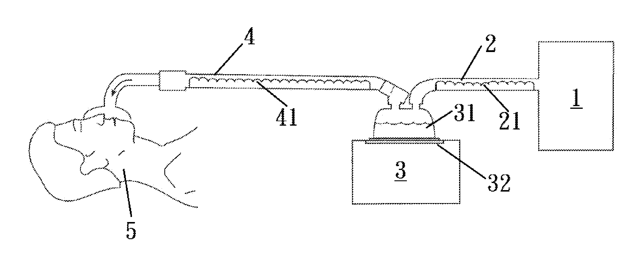
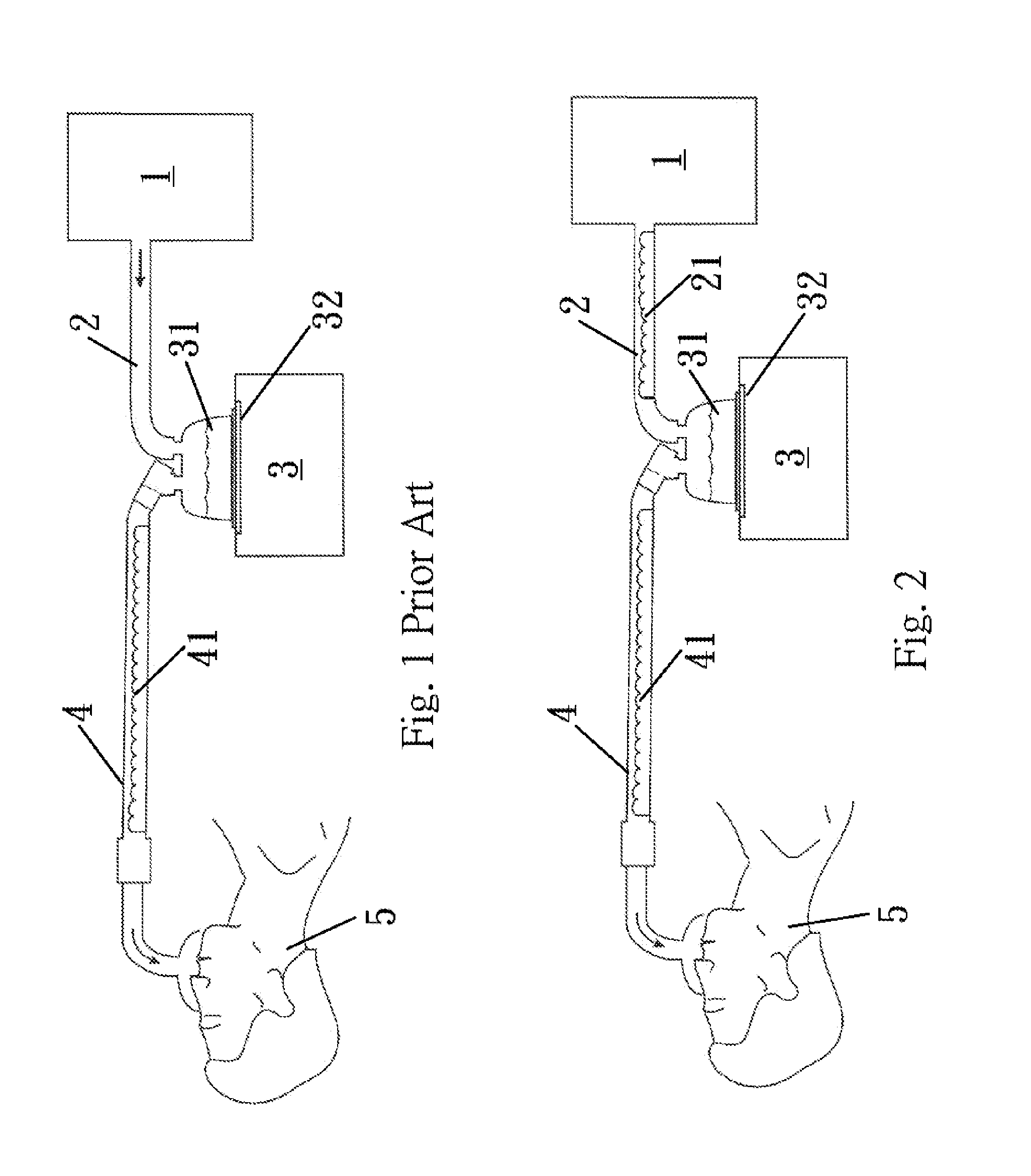
[0017]Please refer to FIG. 2. A gas supply means, commonly called the air pressure source 1, is built in with a fan or compressor (not shown). The air generated by the air pressure source 1 is sent to a humidifier 3 via a pipeline 2. The humidifier includes a humidification chamber 31 and a heater plate 32. The heater plate 32 heats up the water carrier inside the humidification chamber 31, so that the gas provided by the air pressure source 1 carries away the water vapor from the water carrier. The humidified gas is sent via the intake duct 4 to the patient at the best breathing temperature and humidity. To reduce condensed water, a heating element 41 is provided inside the intake duct to maintain the temperature of the gas.

[0018]The invention is featured in that a heating element 21...


PUM


Abstract

A preheating device is installed to the pipeline connecting between an air pressure source and a humidifier to increase the temperature of the gas entering the humidifier and to reduce the relative humidity. The gas can fully mix with vapor generated by a heated water carrier within a short time, thereby preventing the humidifier from excessively outputting condensed water.

Description

BACKGROUND OF THE INVENTION[0001]1. Field of Invention[0002]The invention relates to a respiratory humidification system and, in particular, to a preheating device interposed between an air pressure source and a humidifier in order to preventing the humidifier from excessively outputting condensed water.[0003]2. Related Art[0004]The humidification apparatus or respiratory humidification system is common medical equipment for the hospital emergency room and intensive care unit. When a patient is unable to breathe, or can breathe on his own but cannot reach the concentration of oxygen needed by the body, the humidification apparatus is then required to sustain life. This applies in particular to patients with lung diseases, such as SARS, H1N1, or patients who have experienced a lung injury.[0005]FIG. 1 shows the functional principle of a humidification apparatus. A gas supply means, commonly known as air pressure source, is built in with a fan or compressor (not shown). The air thus g...

Claims


Application Information

Patent Timeline
IPC IPC(8): A61M16/10A61M16/00A61M16/08A61M16/16
CPCA61M16/109A61M16/16A61M16/0875A61M16/0066A61M16/108A61M16/1085A61M16/1095
Inventor HUANG, NEO
Owner HUANG NEO
Why Eureka
Try Eureka