3D Shielding Case and Methods for Forming the Same

a shielding case and shielding technology, applied in the direction of magnetic/electric field screening, basic electric elements, solid-state devices, etc., can solve the problems of increasing the manufacturing cost of integrated circuits, affecting the quality of shielding,

Active Publication Date: 2014-09-18
TAIWAN SEMICON MFG CO LTD
View PDF9 Cites 73 Cited by
  • Summary
  • Abstract
  • Description
  • Claims
  • Application Information

AI Technical Summary

Problems solved by technology

Electro-Magnetic Interference (EMI) is a common problem in the applications of integrated circuits.
The EMI becomes a more severe issue in the applications in which high frequencies

Method used


Image

  • 3D Shielding Case and Methods for Forming the Same
  • 3D Shielding Case and Methods for Forming the Same
  • 3D Shielding Case and Methods for Forming the Same

Examples


Embodiment Construction

[0008]The making and using of the embodiments of the disclosure are discussed in detail below. It should be appreciated, however, that the embodiments provide many applicable concepts that can be embodied in a wide variety of specific contexts. The specific embodiments discussed are illustrative, and do not limit the scope of the disclosure.

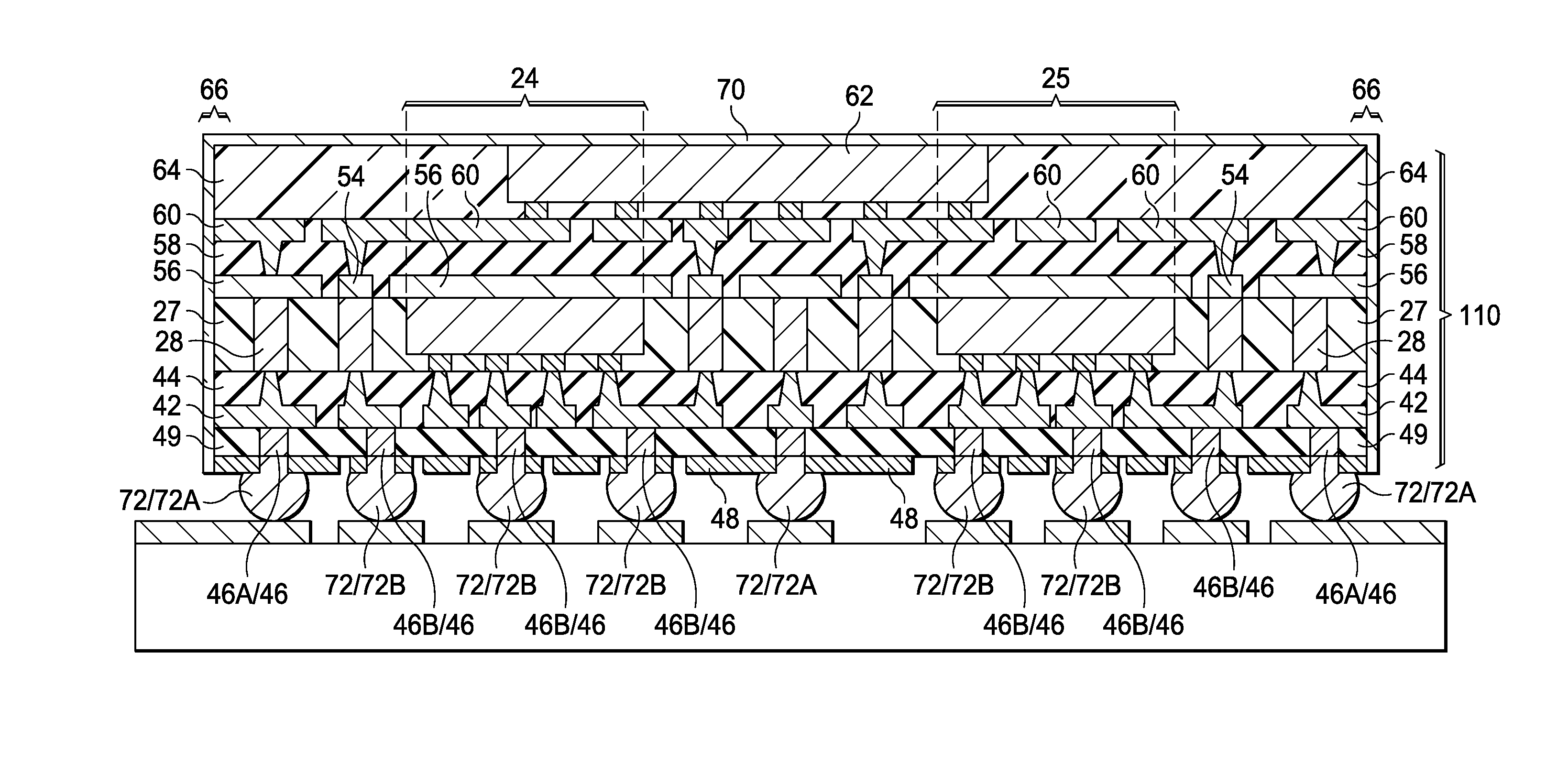
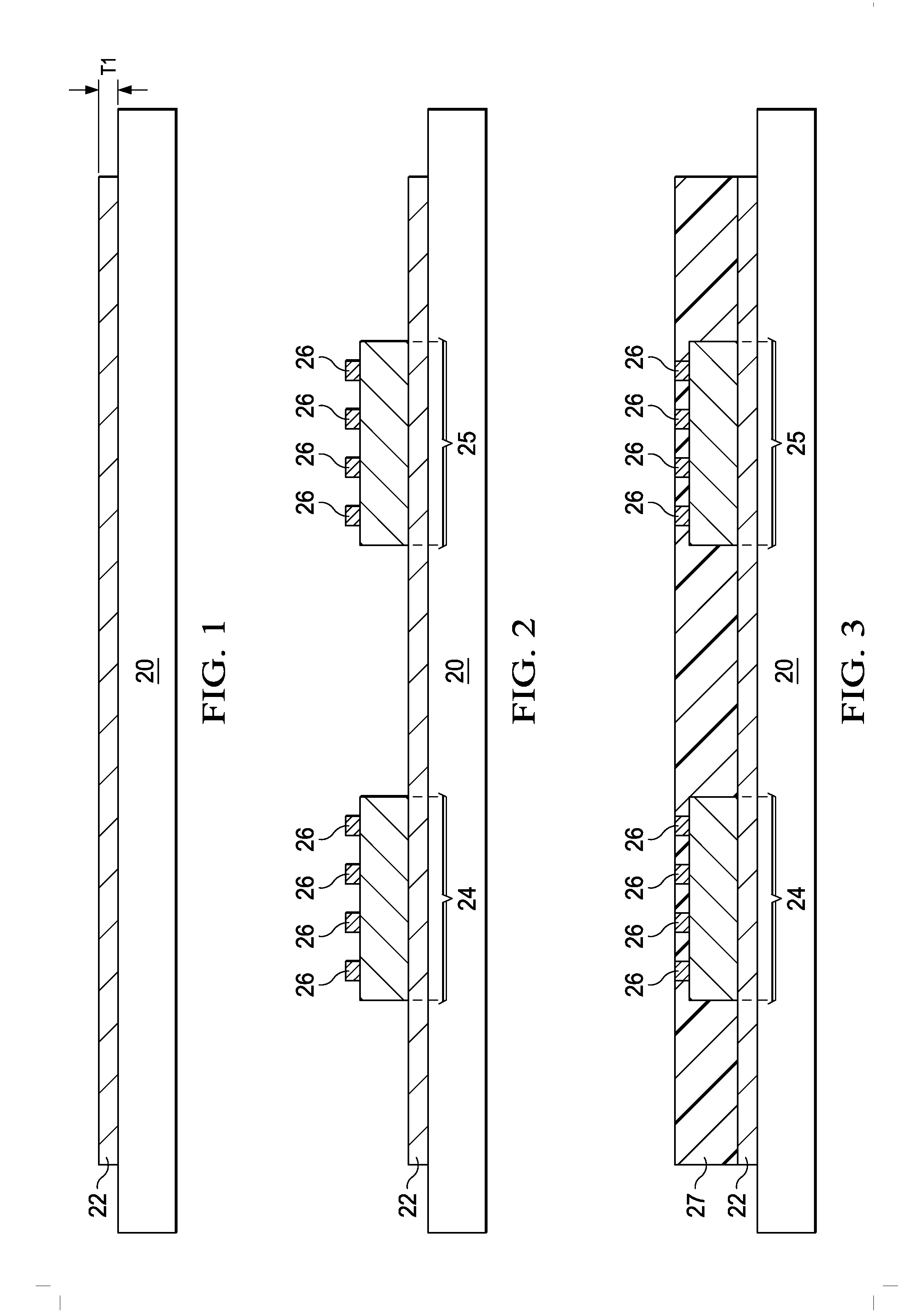
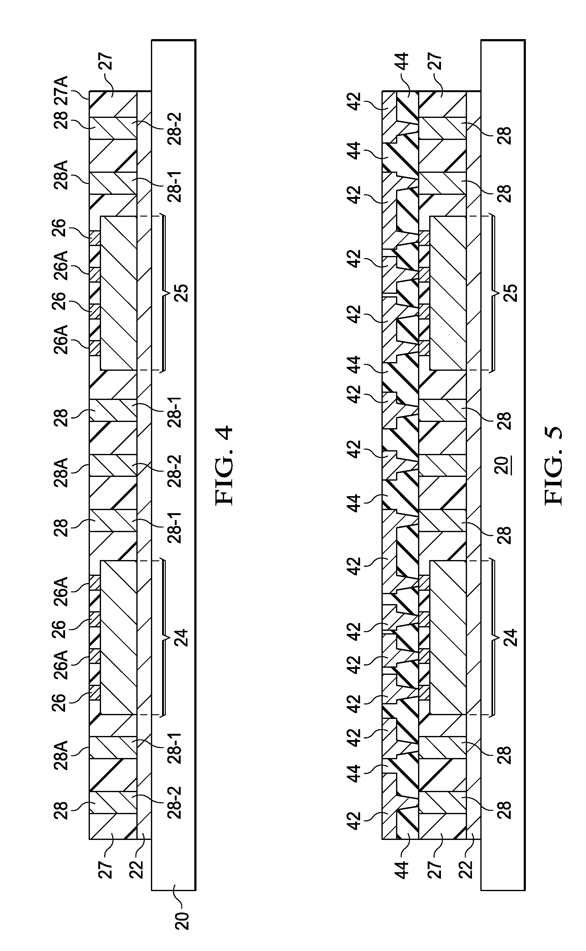
[0009]A built-in metal shielding case and the method of forming the same are provided in accordance with various exemplary embodiments. The intermediate stages of forming the metal shielding case in a packaging process are illustrated. The variations of the metal shielding case are discussed. Throughout the various views and illustrative embodiments, like reference numbers are used to designate like elements.

[0010]FIGS. 1 through 15 are cross-sectional views and top views of intermediate stages in the manufacturing of a package including a built-in metal shielding case in accordance with some exemplary embodiments. FIG. 1 illustrates carrier 20, ...


PUM


Abstract

A package includes a die, and a molding material molding the die therein. A metal shield case includes a first metal mesh over and contacting the molding material and the die, a second metal mesh underlying the die, and a Through-Assembly Via (TAV) in the molding material and forming a ring encircling the die. The TAV is electrically connected to the first metal mesh and the second metal mesh.

Description

[0001]This application claims the benefit of U.S. Provisional Application No. 61 / 778,291, filed on Mar. 12, 2013, and entitled “3D Shielding Case and Methods for Forming the Same,” which application is hereby incorporated herein by reference.BACKGROUND[0002]Electro-Magnetic Interference (EMI) is a common problem in the applications of integrated circuits. The EMI becomes a more severe issue in the applications in which high frequencies are used, for example, in mobile applications in which Radio Frequency (RF) signals are used.[0003]To reduce the EMI between device dies, metal shielding cases are used to shield the device dies. The metal shielding cases are typically formed of iron using stamping process. The metal shielding cases are designed to fit the sizes and the shapes of the device dies that are to be shielded. After the dies are bonded to a Printed Circuit Board, the metal shielding cases are covered on the dies, and are soldered to the PCB. The metal shielding cases provide...

Claims


Application Information

Patent Timeline
IPC IPC(8): H05K9/00
CPCH05K9/0007H01L21/568H01L21/6835H01L23/49816H01L23/5384H01L23/5389H01L23/552H01L24/16H01L24/19H01L24/32H01L24/73H01L24/81H01L24/92H01L2221/68372H01L2224/12105H01L2224/16225H01L2224/32245H01L2224/73253H01L2224/73267H01L2224/81005H01L2224/92244H01L2924/14H01L2924/1431H01L2924/15311H01L2924/181H01L2924/18161Y10T29/49117H01L2924/00H01L23/66H01L21/4817H01L21/4846H01L21/4853H01L21/486H01L21/565H01L25/50H01L2225/06517H01L2225/06527H01L2225/06544H01L2225/06582
Inventor LIU, MONSENWANG, CHUEI-TANGCHIH, LAI WEIYU, CHEN-HUA
Owner TAIWAN SEMICON MFG CO LTD
Why Eureka
Try Eureka