Substrate support bushing

a technology of supporting bushings and supporting pins, which is applied in the direction of coupling device connections, manufacturing tools, transportation and packaging, etc., can solve the problems of lifting pins choking, film deposition may also inadvertently occur on the inside of the supporting pin, and tendencies to bend or til

Active Publication Date: 2014-09-18
APPLIED MATERIALS INC
View PDF39 Cites 196 Cited by
  • Summary
  • Abstract
  • Description
  • Claims
  • Application Information

AI Technical Summary

Benefits of technology

[0010]In a yet another embodiment, a processing chamber is provided. The processing chamber includes a chamber body having a substrate support pedestal disposed therein, and two or more support bushings. The two or more support members are each disposed on an upper surface of the support pedestal. The support members comprise a housing having a bore formed therethro...

Problems solved by technology

In conventional deposition chambers, the lift pins are usually housed in a bushing disposed in the support pedestal and have a tendency to bend or tilt in the bushing after repetitive loading and unloading of the substrates.
Film deposition may also inadvertently occur on the inside of the bushing since the bushing is exposed to process gasses used during...

Method used


Image

  • Substrate support bushing
  • Substrate support bushing
  • Substrate support bushing

Examples


Embodiment Construction

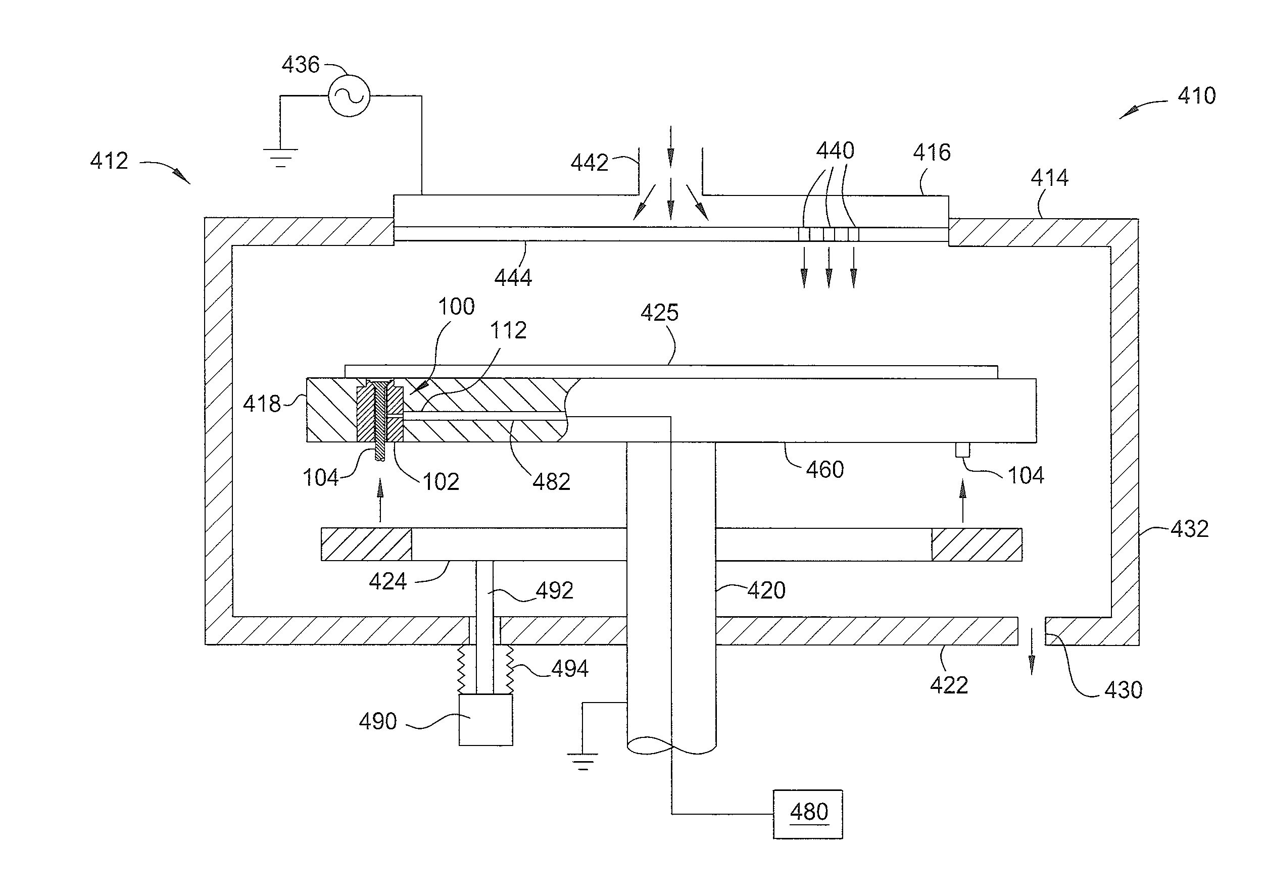
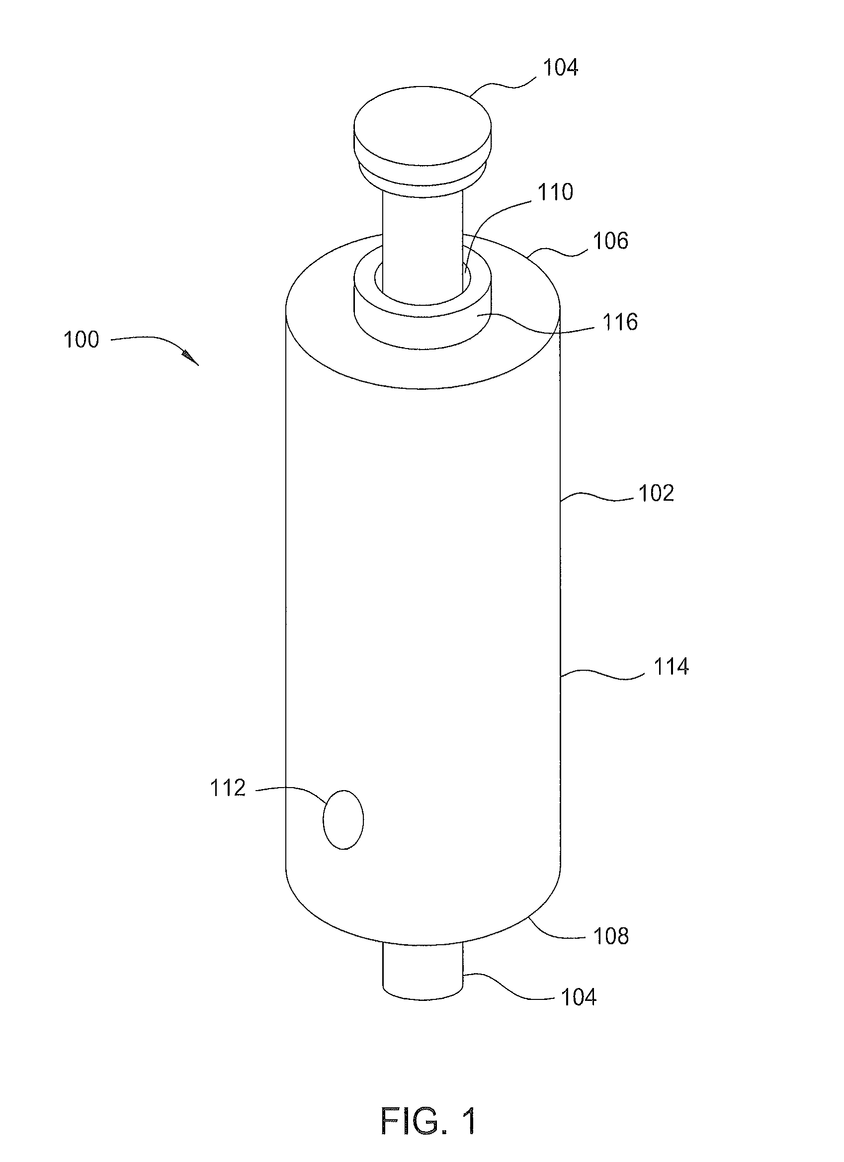
[0022]FIG. 1 is a schematic perspective view of one embodiment of a support member 100. The support member 100 includes a bushing 102 and a lift pin 104 disposed therethrough. At a first end 106 of the support member 100, a substrate (not shown), such as any semiconductor substrate including a flat panel display, round wafer, liquid crystal display, glass panel substrate, plastic substrate, and the like, may be supported on the lift pin 104. At a second and 108 of the support member 100, the support member 100 may be coupled to a support pedestal, susceptor, robot blade, shelf, or other member adapted to hold or support a substrate thereon.

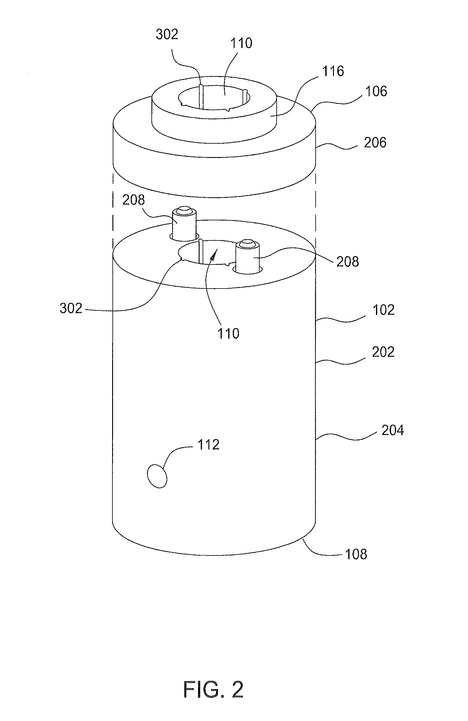
[0023]In one embodiment, the bushing 102 is cylindrical. The bushing 102 has an annular elongated body 114 having a central bore 110 and across hole 112 formed at least partially therethrough. The body 114 may be fabricated from a metal, plastic of other suitable material. In one embodiment, the body 114 is fabricated from ceramic, or a material h...


PUM


Abstract

In one embodiment, a substrate support bushing for a lift pin used in a semiconductor processing chamber is provided. The bushing includes an elongated housing sized to guide the lift pin in a substrate support pedestal. The housing has a longitudinal bore formed through the housing. The housing includes at least one passageway slot extending and open to substantially the entire length of the bore. In another embodiment, a method for transferring a substrate from a substrate support pedestal is provided. The method includes displacing a lift pin through a central bore toward a substrate disposed on a substrate support pedestal. The bore has at least one slot extending substantially along and open to the central bore. The method further includes spacing the substrate from the substrate support pedestal on the lift pin.

Description

CROSS-REFERENCE TO RELATED APPLICATIONS[0001]This application claims priority to U.S. Provisional Patent Application Ser. No. 61 / 784,210, filed on Mar. 14, 2013, which is incorporated by reference in its entirety.BACKGROUND OF THE INVENTION[0002]1. Field of the Invention[0003]Embodiments of the present invention generally relate to a substrate support bushing. More particularly, embodiments of the present invention relate to a substrate support bushing for use with a lift pin in substrate support pedestal.[0004]2. Description of the Related Art[0005]Thin film transistors have been made on large glass substrates or plates for use in monitors, flat panel displays, solar cells, personal digital assistants (PDA), cell phones, and the like. These transistors are made by sequential deposition of various films including amorphous silicon, both doped and undoped silicon oxides, silicon nitride, and the like in vacuum chambers. The film deposition takes place in a deposition chamber. Within ...

Claims


Application Information

Patent Timeline
IPC IPC(8): H01L21/687
CPCH01L21/68742H01L21/68785H01L21/68771H01L21/67115
Inventor HOU, TAO
Owner APPLIED MATERIALS INC
Why Eureka
Try Eureka