Adaptive connector

Inactive Publication Date: 2014-09-18
SMITHS MEDICAL ASD INC
View PDF0 Cites 18 Cited by
  • Summary
  • Abstract
  • Description
  • Claims
  • Application Information

AI Technical Summary

Benefits of technology

[0006]At the respective ends of the members not connected together there are provided different types of connector fittings or the same connector fitting. One of the fittings is a conventional fitting such as a female luer connector that is matable to a counterpart conventional fitting such as a male luer connector of one device. The other connector fitting is a non-conventional fitting, for example a male CorrectInject™ (CI) connector, that is matable only to a counterpart non-conventional fitting, i.e., a female CorrectInject™ (CI) connector, of another device. Both the male and female CI connectors are manufactured by the assignee of the instant application. An elastomeric seal such as a silicone O-ring is positioned at or proximate to the interface of the through passages of the two mated members to prevent fluid leakage from the adapter. An alternative embodiment of the inventive connector has both of its fittings being conventional fittings, i.e., luer fittings, so that the connector may be advantageously used as an intermediary to connect devices that have counterpart conventional connector fittings.
[0009]The instant invention is therefore directed to a connector for connecting devices having conventional and / or non-conventional fittings to effect a fluid path between the fittings. The connector has a first member having a first through passage, a first coupling mechanism, a first distal portion with a distal end and a first proximal portion with a first proximal end including a first fitting matable with a counterpart first fitting of a first device. The connector further has a second member having a second distal portion with a second distal end and a second proximal portion connectable to the first distal portion. The second proximal portion has an inner diameter larger than the outer diameter of the first distal portion so that the first distal portion is inserted into or matable with the second proximal portion. A second through passage extends along the second distal portion and a second coupling mechanism is formed internally in the second proximal portion. A second distal end of the second member includes a conventional or non-conventional second fitting that is matable with a counterpart conventional or non-conventional fitting. When the first distal portion is matingly coupled to the second proximal portion, the first and second coupling mechanisms are non-removably engaged to each other with the first and second through passages in alignment to establish a fluid through channel across the first and second members. An O-ring is positioned in intimate contact with the first distal portion and the second proximal portion to effect a fluid tight seal for the connector. A ratchet mechanism in the adapter enables the selective rotation of the members of the connector.
[0011]The present invention is also directed to a connector adapted to connect devices with conventional and / or non-conventional connector fittings that are not matable to each other. The connector has a first member having a first through passage, a first coupling mechanism and a first fitting at a first proximal end for mating with a counterpart first connector fitting of a first device. The connector further has a second member having a second through passage, a second coupling mechanism and a second fitting at a second distal end for mating with a counterpart second connector fitting of a second device. The first and second through passages are positioned in alignment along a longitudinal axis when the first and second members are connected to each other with the first and second coupling mechanisms engaged, so that the in-alignment first and second through passages effect a through channel across the first and second members to enable the exchange of fluid between the first and second devices when the first and second devices are mated to the first and second members, respectively. A seal may be provided in the connector to prevent fluid leak. A ratchet mechanism may be provided in the connector to enable the first and second members to rotate in unison when either of the members is rotated in one direction relative to the other, and each rotate independently of the other when either of the members is rotated in an opposite direction relative to the other. The one and other directions may also be referred to as the clockwise and counterclockwise rotation or direction.
[0012]The connector of the instant invention is also adapted to connect one device with a conventional connector fitting and an other device with a non-conventional connector fitting so that the one and other devices that otherwise are not connectable to each other may nonetheless be connected via the connector so that a fluid path may be established between the one and other devices. Conversely, the inventive connector prevents the inadvertent connection of a device, for example a medical syringe, to another device, for example a medical needle, that were not meant to be connected together, to thereby prevent mis-connection of the devices.
[0019]The inventive method also includes the steps of providing a seal to prevent fluid leakage from the connector, and providing a ratchet mechanism in the connector to selectively enable the members of the connector to rotate in unison in one direction but rotate independently of each other when either of the members is rotated in an opposite direction relative to the other.
[0020]In an alternative embodiment, the connector may have conventional connector fittings at the respective ends of the members that are not coupled to each other so that the connector may act as a bridge for devices with conventional fittings where it may be advantageous to have one of the devices non-removably connected to the connector and the other of the devices removably connectable to the one device. This obviates the need to have the two devices connected directly to each other, as the connector of the instant invention provides a robust connector bridge for the devices in the event that it may not be a good idea to repeatedly connect / disconnect the conventional connector fitting of one of the devices to the conventional connector fitting of the other device.

Problems solved by technology

Due to possible mis-tolerance during the manufacturing of the components, friction that may result from the interaction between the components, and / or possible material dissimilarities of the mating to the components that cause the components to stick, there are instances where the rotation of one device connected to one end of the adapter may cause rotation of the other device connected to the other end of the adapter.

Method used


Image

  • Adaptive connector
  • Adaptive connector
  • Adaptive connector

Examples


Embodiment Construction

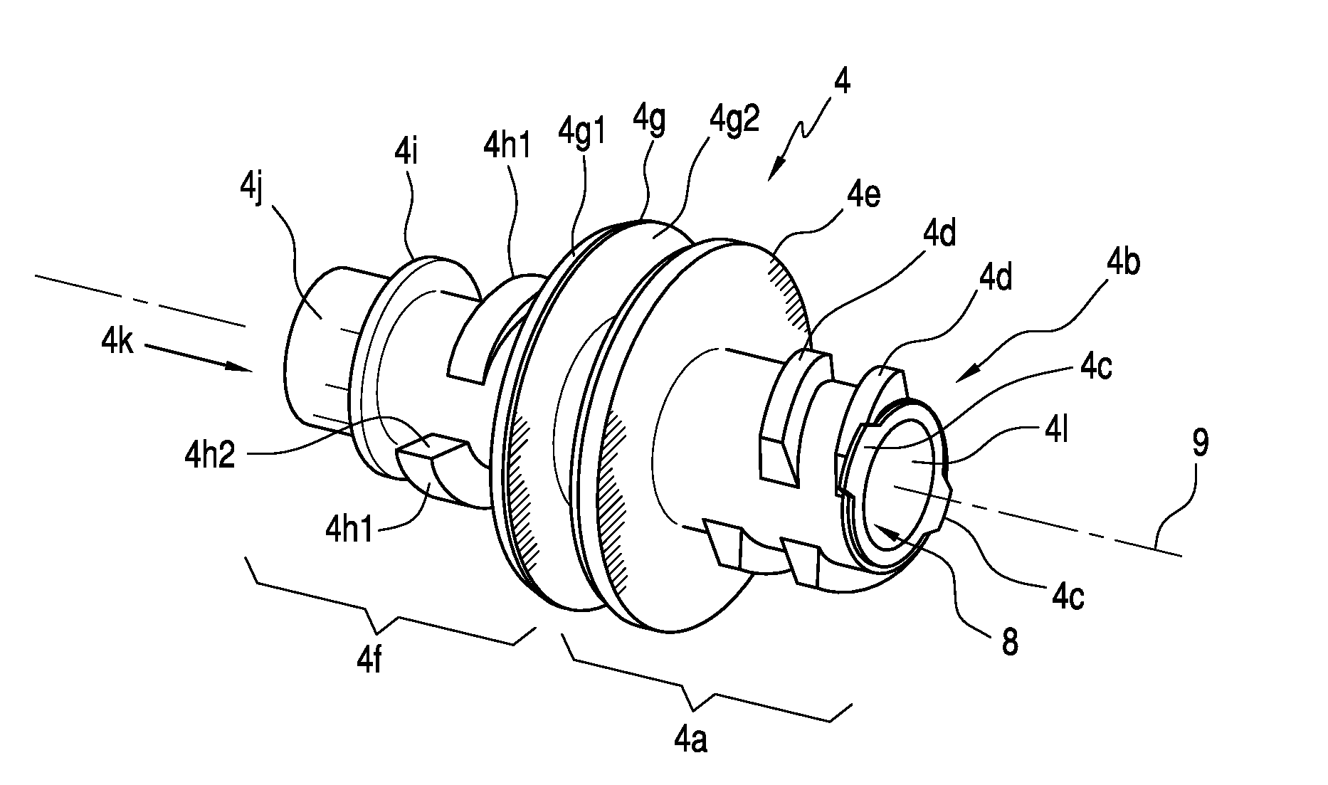
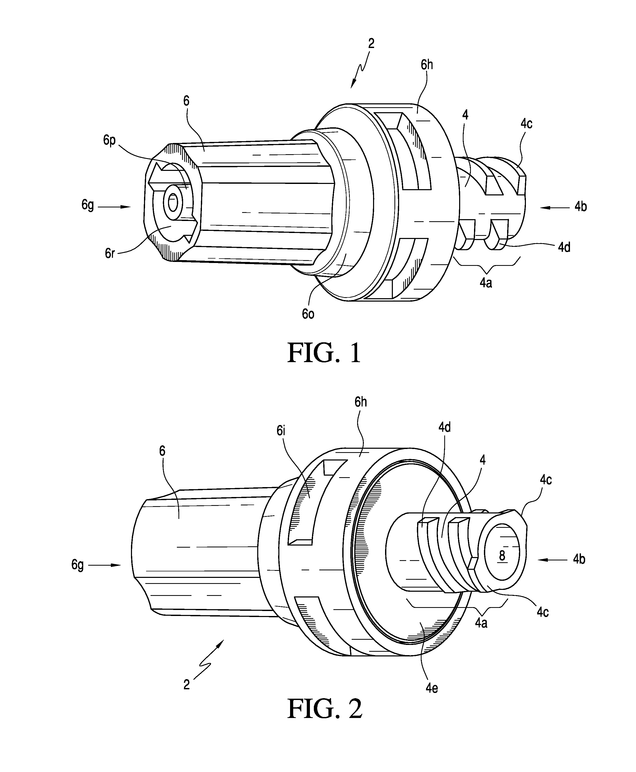
[0037]With reference to FIGS. 1 and 2, the fitting adapter or connector 2 of the instant invention is shown to include a first member 4 having a conventional female luer connector and a second member 6 having a non-conventional male CorrectInject™ (CI) connector non-removably mated to each other. For the embodiment shown in FIGS. 1 and 2, first member 4 may be referred to as a female luer member insofar as it has a proximal portion 4a with a proximal end 4b configured in the form of a conventional female luer fitting that includes a helical thread that may be formed as a non-continuous thread for ease of manufacture. The helical thread is represented by partial threads 4c and 4d. Thus configured, the conventional female luer of first member 4 is adapted to be connected to or matable with a counterpart conventional fitting, i.e., a conventional male luer connector, of a device such as for example a medical device that includes a syringe, a fluid line or a fluid store including a medi...


PUM


Abstract

A connector has a first member with a distal portion non-removably coupled to a proximal portion of a second member. Respective through passages at the first and second members are in alignment to establish a through channel longitudinally along the connector. A seal in the connector prevents fluid leakage from the connector. A conventional fitting may be provided at one of the ends and a non-conventional fitting may be provided at the other end of the connector so that the connector may connect a device with a conventional fitting to a device with a non-conventional fitting. Once connected to the connector, the device with the conventional fitting is not removable from the connector. The first and second members are rotatable relative to each other about the longitudinal axis of the connector to enable rotational alignment of devices connected to the connector.

Description

FIELD OF THE INVENTION[0001]The present invention relates to an connector or fitting adapter that is adapted to connect devices that have connector fittings that are not directly connectable to each other, and also act as an intermediary connector to devices with connector fittings.BACKGROUND OF THE INVENTION[0002]To prevent mis-connection of a fluid line or a fluid store containing a particular medication to a needle and / or an infusion line, the prior art discloses the use of a two part connector with complementary configured opposing surfaces. Such two part connector is disclosed in U.S. Pat. No. 6,612,624 and its parent U.S. Pat. No. 6,402,207.[0003]U.S. Pat. No. 7,497,484, assigned to the assignee of the instant application, discloses a three component connector or fitting adapter for connecting devices with different connector fittings that include a shroud, an inner shroud and a core. US application No. 11 / 342,620, filed Jan. 31, 2006, published as US 2007 / 0179454, also assign...

Claims


Application Information

Patent Timeline
Patent Type & Authority Applications(United States)
IPC IPC(8): A61M39/10
CPCA61M2039/1027A61M39/1011
Inventor CLARK, GEOFFKENNELLY, J. MICHAEL
Owner SMITHS MEDICAL ASD INC
Why Eureka
Try Eureka