Method and System for Random Steerable Sar Using Compressive Sensing

a random steering and sensing technology, applied in the field of synthetic aperture radar systems, can solve the problems of difficult to achieve in a conventional sar system with a single baseline observation, and achieve the effects of increasing imaging resolution, flexible steering, and same coverag

Active Publication Date: 2014-09-18
MITSUBISHI ELECTRIC RES LAB INC
View PDF8 Cites 49 Cited by
  • Summary
  • Abstract
  • Description
  • Claims
  • Application Information

AI Technical Summary

Benefits of technology

[0016]The purpose of the system and method described here is to increase imaging resolution while maintain the same coverage. The system and method described here incorporates more flexible steering. Instead of partitioning the scene into a small number of spots, now at each pulse transmission, the beam center is steered randomly such that the beam covers a spot randomly located uniformly within the imaged

Problems solved by technology

This is difficult to achieve in a conventional

Method used


Image

  • Method and System for Random Steerable Sar Using Compressive Sensing
  • Method and System for Random Steerable Sar Using Compressive Sensing
  • Method and System for Random Steerable Sar Using Compressive Sensing

Examples


Embodiment Construction

[0023]The embodiments of our invention provide a system and method for generating an image, wherein the image is a synthetic aperture radar (SAR) image. The embodiments on the CS-based image reconstruction process assume steerable beam of pulses. This can be realized by controlling the beam-pattern electronically, or by steering an array of antennas, mechanically.

[0024]By decomposing the underlying SAR image into sparse part and dense part, our imaging method reconstructs the sparse part using CS, and estimates the dense part using a least squares method. The incorporation of sparse modeling and least squares method outperforms conventional CS techniques using only sparsity regularization.

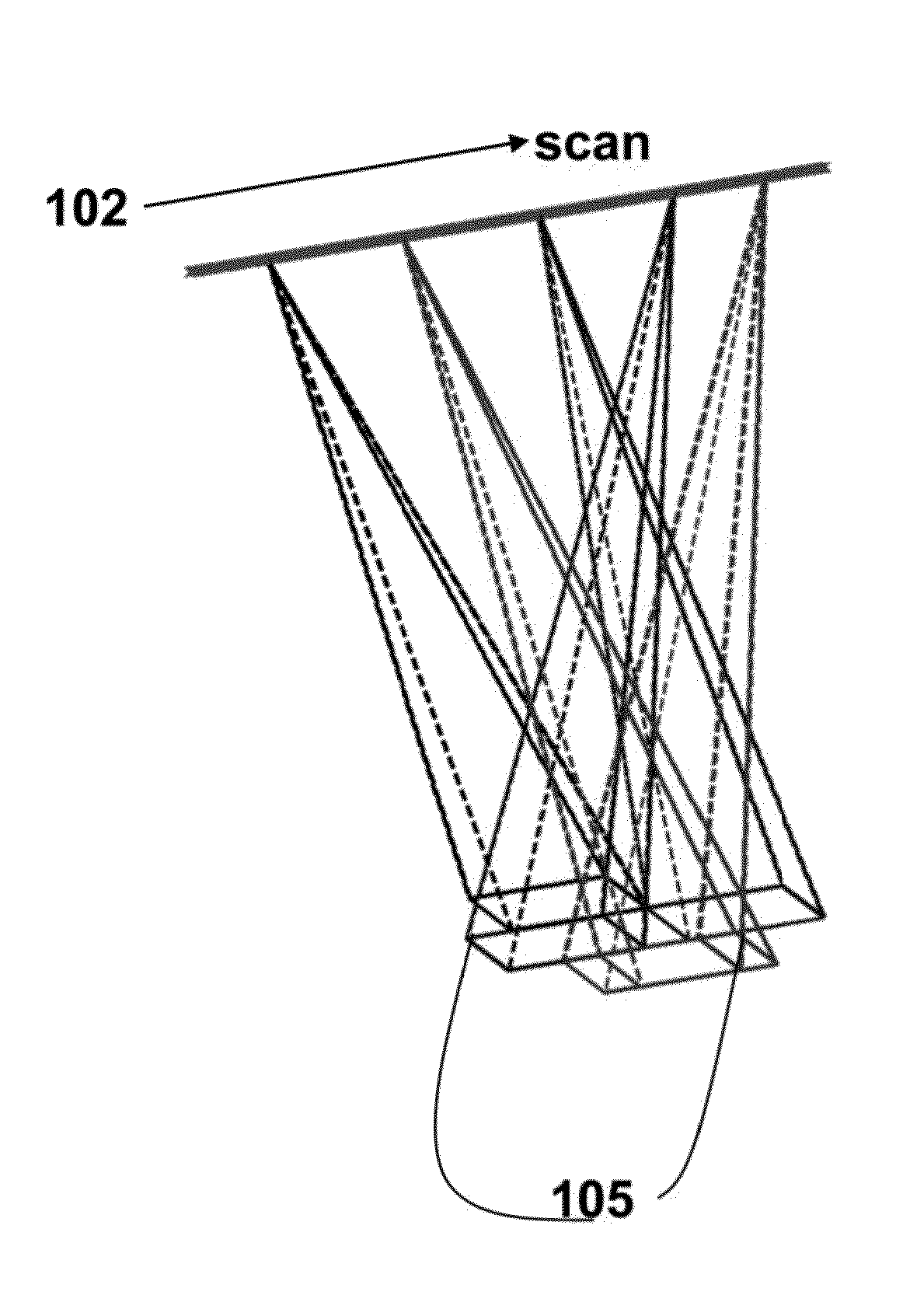
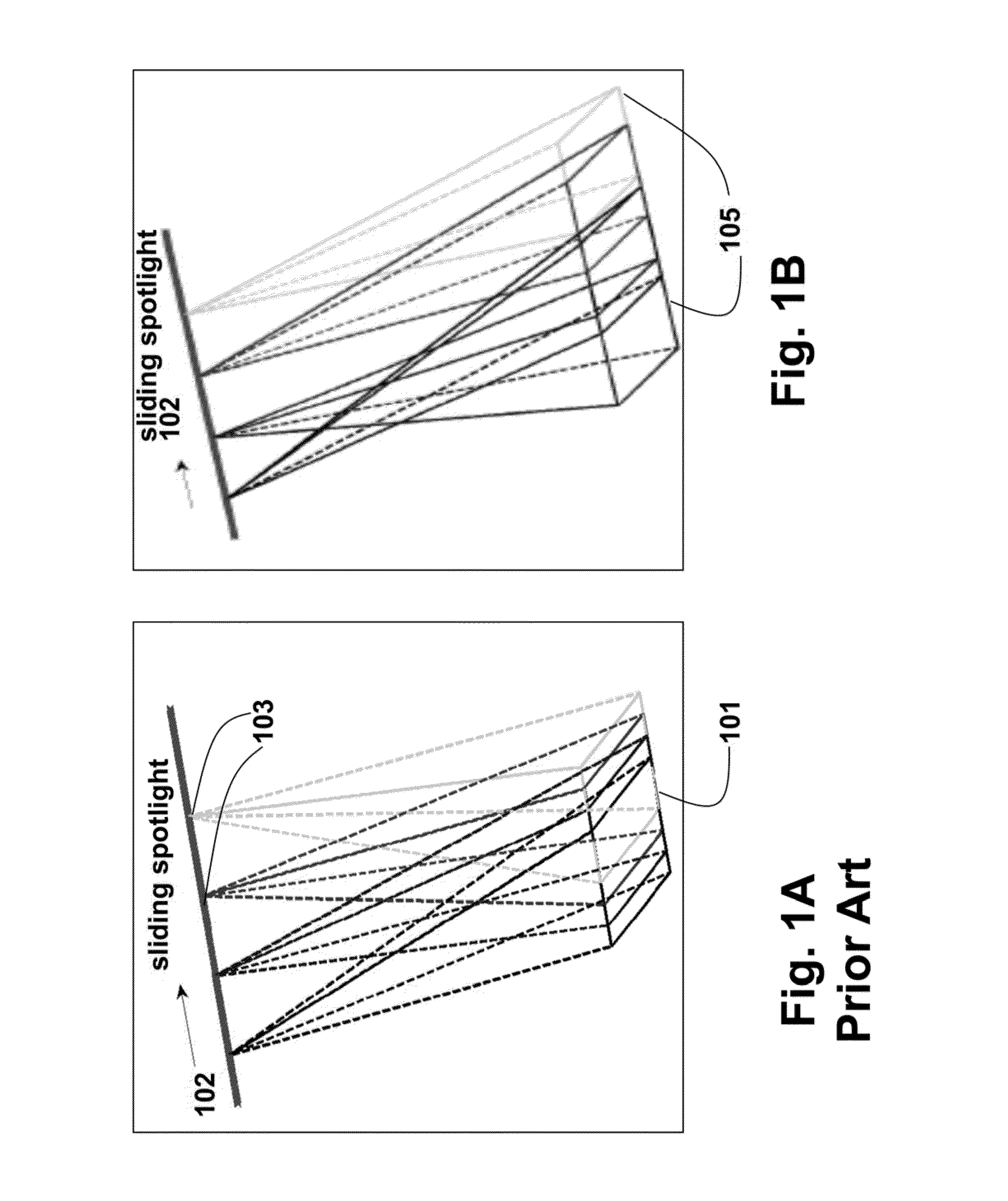
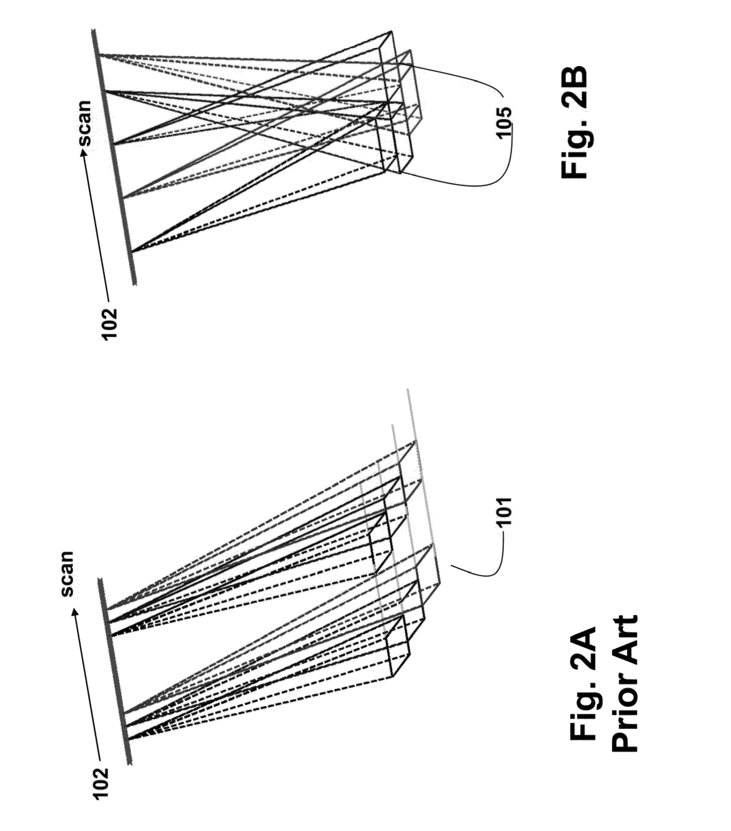
[0025]As shown in FIG. 1A, a conventional linear mono-static uniform virtual array operating in sliding spotlight mode. FIG. 2A shows a conventional system operating in scan. To image an area or scene 101, a mobile radar platform moves along the path 102 while transmitting pulse 103 at a uniform pu...


PUM


Abstract

A synthetic aperture radar image is generated by directing randomly a beam of transmitted pulses at an area using a steerable array of antennas, wherein the area is uniformly by the transmitted pulses while the array of antennas moves along a path. A sparse reconstruction procedure is applied to received signals from the area due to reflecting the transmitted pulses to generate the image corresponding to the area. The radar system can operate in either sliding spotlight mode, or scan mode. The area can be of an arbitrary shape, and a resolution of the image can be increased.

Description

FIELD OF THE INVENTION[0001]This invention relates generally to synthetic aperture radar systems, and more particularly to scan mode and sliding spotlight mode radar systems.BACKGROUND OF THE INVENTION[0002]Monostatic synthetic aperture radar (SAR) systems provide a tradeoff between imaging resolution and ground area coverage. In strip-map SAR, the radar antenna is pointed at an area as the platform carrying the antenna moves along a path, collecting data to generate a radar image of a certain resolution and area size.[0003]To meet different application requirements on imaging resolution and area coverage, radar antennas can also be steered, either electronically or mechanically, in different modes. When higher imaging resolution is required, the SAR system operates in spotlight mode by steering the antenna to always illuminate the same spot of interest, generating an image with higher imaging resolution and smaller coverage compared to strip-map mode SAR.[0004]Intermediate SAR mode...

Claims


Application Information

Patent Timeline
IPC IPC(8): G01S13/90
CPCG01S13/9035G01S13/904G01S13/9052G01S13/9056
Inventor LIU, DEHONGBOUFOUNOS, PETROS T
Owner MITSUBISHI ELECTRIC RES LAB INC
Why Eureka
Try Eureka