
Mode Filter

a filter and mode technology, applied in the field of mode filters, can solve the problems of compromising the radiation pattern of the antenna, large waveguide structures, and relatively bulky, and achieve the effect of excellent mode suppression characteristics

Active Publication Date: 2014-09-18
MAXAR SPACE LLC
View PDF5 Cites 7 Cited by
  • Summary
  • Abstract
  • Description
  • Claims
  • Application Information

AI Technical Summary

Benefits of technology

The present invention is about a mode filter that can suppress unwanted modes of electromagnetic signals. This filter can be made compact and conductive, without using non-conductive materials. The mode filter has an internal cross-section that is non-uniform and can effectively suppress at least two undesired modes. This helps to improve the quality of signals and reduce interference.

Problems solved by technology

This can compromise the radiation pattern of the antenna, particularly in terms of cross polarization.
However, this results in expensive and big waveguide structures.
For example, some prior art filters may provide good mode suppression but are relatively bulky, are made of multiple parts, and may be difficult to manufacture and / or integrate.

Method used


Image

  • Mode Filter
  • Mode Filter
  • Mode Filter

Examples


Embodiment Construction

[0028]Specific exemplary embodiments of the invention will now be described with reference to the accompanying drawings. This invention may, however, be embodied in many different forms, and should not be construed as limited to the embodiments set forth herein. Rather, these embodiments are provided so that this disclosure will be thorough and complete, and will fully convey the scope of the invention to those skilled in the art.

[0029]It will be understood that when an element is referred to as being “connected” or “coupled” to another element, it can be directly connected or coupled to the other element, or intervening elements may be present. Furthermore, “connected” or “coupled” as used herein may include wirelessly connected or coupled. It will be understood that although the terms “first” and “second” are used herein to describe various elements, these elements should not be limited by these terms. These terms are used only to distinguish one element from another element. Thus...


PUM


Abstract

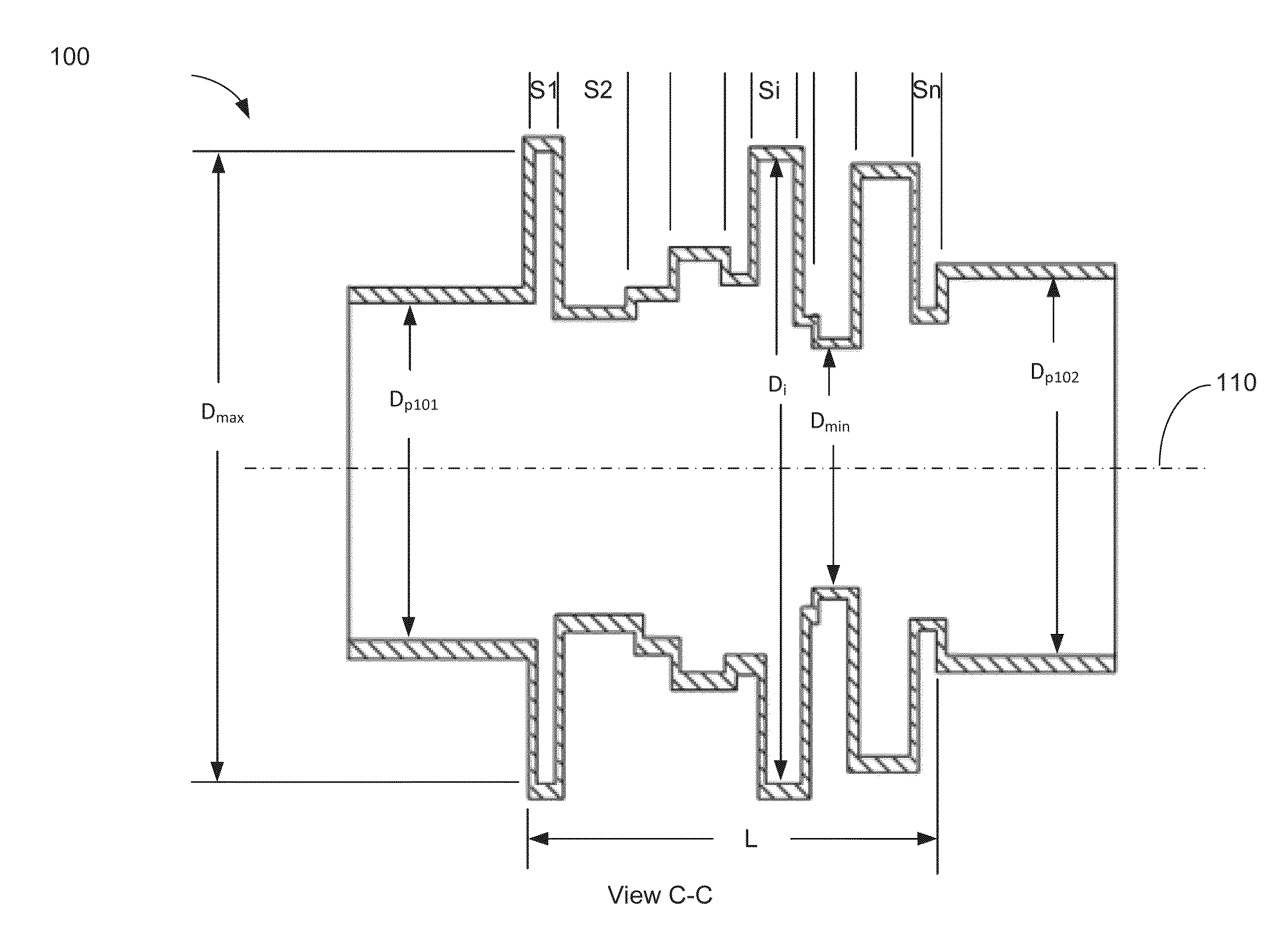
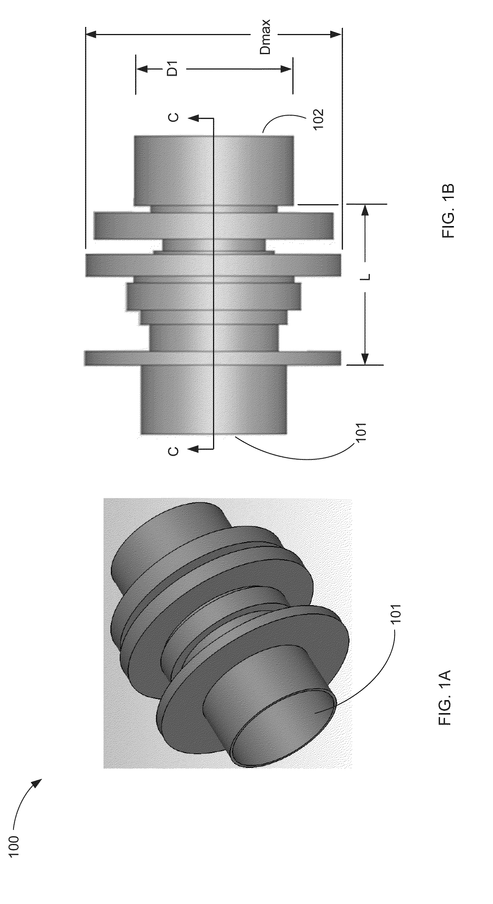
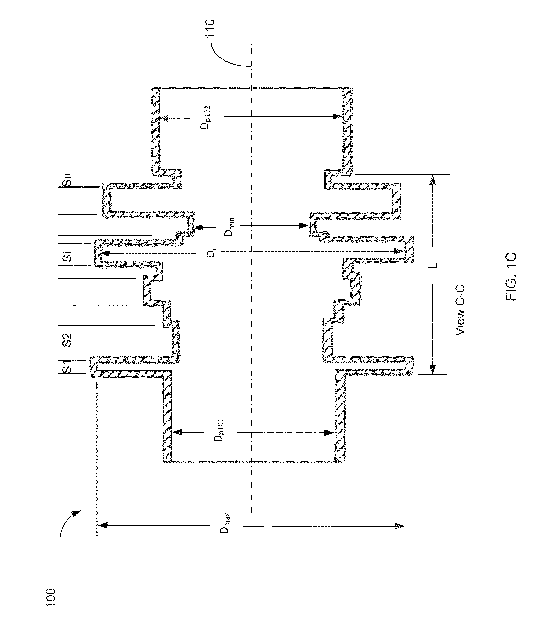
A mode filter provides a low-loss transmission path for RF signals propagating in a first mode, while substantially suppressing at least one second mode. The mode filter includes a proximal port and a distal port, having a respective characteristic cross sectional dimension Dp1 and Dp2, and an electrically conductive hollow tube having a longitudinal axis that extends a length L between a distal end of the proximal port and a proximal end of the distal port. A cross section transverse to the longitudinal axis is non-uniform along length L and has a minimum internal characteristic dimension Dmin at least at a first longitudinal position and a maximum internal characteristic dimension Dmax at least at a second longitudinal position. The mode filter is configured to suppress the at least one second mode by at least 5 dB, and Dmax is less than 2.5 times the greater of Dp1 and Dp2.

Description

TECHNICAL FIELD[0001]This disclosure relates to a mode filter, and, more particularly, to a filter for suppressing undesired propagating modes of a microwave signal.BACKGROUND OF THE INVENTION[0002]The assignee of the present invention manufactures and deploys spacecraft for, inter alia, communications and broadcast services. Payload systems for such spacecraft may include high power microwave radio frequency (RF) components such as travelling wave tube amplifiers (TWTA's) and feed networks that are connected by waveguides to radiating elements such as horn antennas and antenna feed elements.[0003]For any mode of transmission of a microwave signal in a waveguide, the electric and magnetic transverse fields may each be resolved into a respective set of tangential and radial components. For a circular waveguide, for example, the tangential and radial components may vary periodically in amplitude along a circular path which is concentric with the wall of the waveguide and may also vary...

Claims


Application Information

Patent Timeline
IPC IPC(8): H01P1/207
CPCH01P1/207H01P1/208H01P1/211
Inventor TAVASSOLI HOZOURI, BEHZAD
Owner MAXAR SPACE LLC
Learn More