Rotating drum collimator

Inactive Publication Date: 2014-09-18
NEMETH LEE L +1
View PDF6 Cites 8 Cited by
  • Summary
  • Abstract
  • Description
  • Claims
  • Application Information

AI Technical Summary

Benefits of technology

[0007]The present invention is designed to overcome the above noted limitations that are attendant upon the use of conventional collimators and, toward this end, it contemplates the provision of a novel rotating drum collimator that allows for ef

Problems solved by technology

Current collimator designs use a large diameter chopping wheel that has a large mass, and produces a great amount of inertia.
These current collimators require a large amount of space and a great deal of shielding to prevent the energy from scattering towards unwanted objects and/or personnel.
In addition, the large size makes the collimator units extr

Method used


Image

  • Rotating drum collimator
  • Rotating drum collimator
  • Rotating drum collimator

Examples


Embodiment Construction

[0031]The present invention now will be described more fully hereinafter with reference to the accompanying figures, in which exemplary embodiments of the invention are shown. The invention may, however, be embodied in many different forms and should not be construed as limited to the embodiments set forth herein. Like reference numerals refer to like elements throughout.

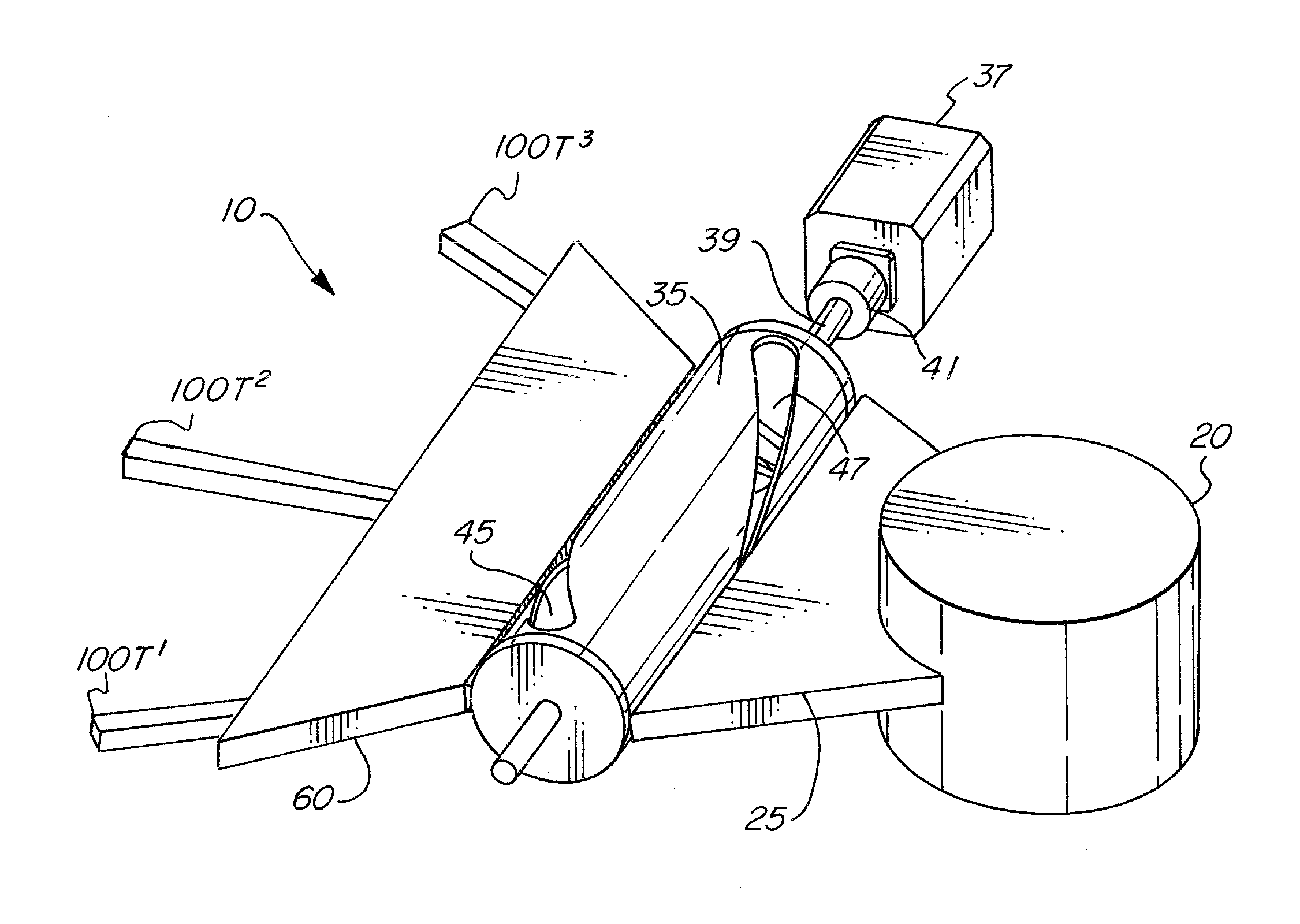
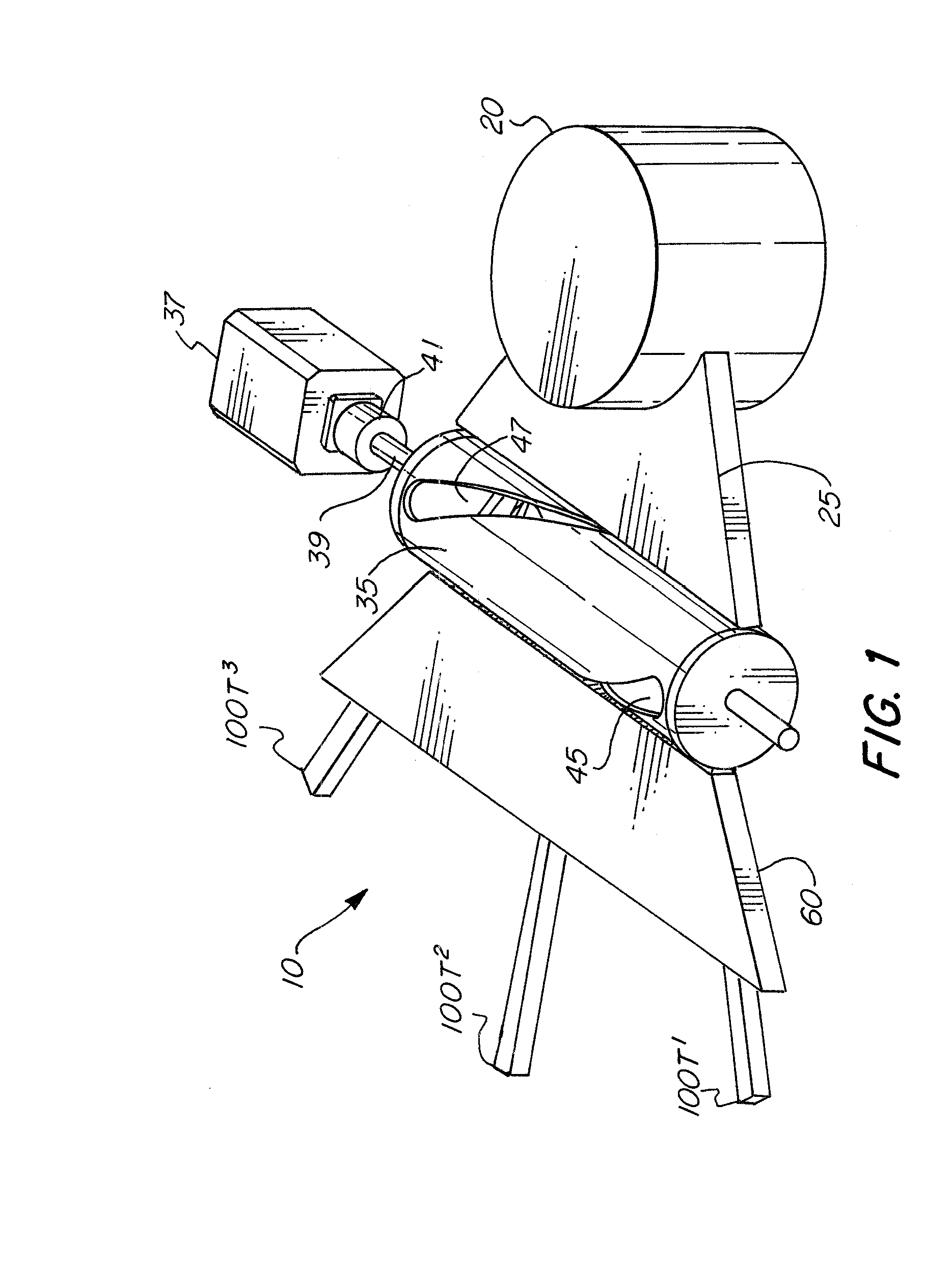
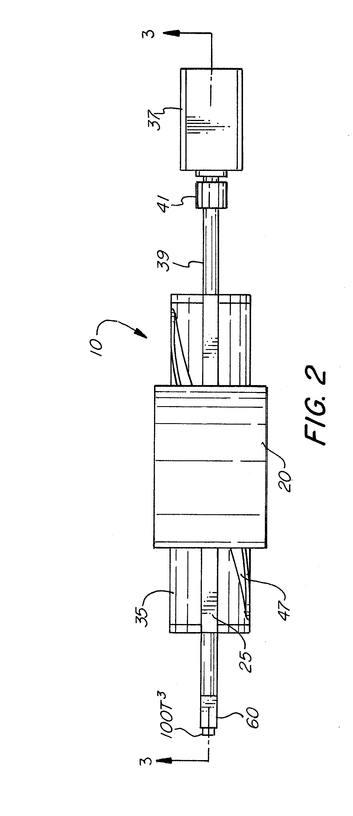
[0032]Referring now to FIGS. 1-3, 3A and 6, therein illustrated is an exemplary embodiment of a rotating drum collimator according to the present invention, generally indicated by reference numeral 10. The rotating drum collimator 10 may include an energy generator 20, for example an X-ray generator, which is configured to generate energy from a particular energy source 22. It is understood that the energy generator 20 may be capable of producing the energy from the energy source 22, or merely a housing for the energy source 22 and configured to direct the energy from the energy source 22 in a desired direction, and...


PUM


Abstract

Exemplary embodiments of the present invention are directed to a rotating drum collimator for collimating an energy beam to produce a scanning beam that includes a drum having a substantially cylindrical sidewall with a first helical groove and a second helical groove formed in the cylindrical side wall, and a motor operatively connected to the drum, and configured to cause rotation of the drum about a longitudinal axis of the drum. Each of the first helical groove and the second helical groove comprises a first end portion, a middle portion and a second end portion, and a width of the first end portion and the second end portion of each of the first helical groove and the second helical groove is greater than the middle portion of each of the first helical groove and the second helical groove.

Description

CROSS-REFERENCE TO RELATED APPLICATIONS[0001]This application claims priority to U.S. Provisional Appl. No. 61 / 784,481 filed Mar. 14, 2013, which is hereby incorporated by reference in its entirety.BACKGROUND OF THE INVENTION[0002]1. Field of the Invention[0003]The present invention is directed to rotating drum collimators, and more particularly to rotating drum collimators that provide for control of a beam along degrees of an arc by manipulating the angular motion of the beam and / or control of the scanning frequency of the beam.[0004]2. Description of Related Art[0005]Current collimator designs use a large diameter chopping wheel that has a large mass, and produces a great amount of inertia. These current collimators require a large amount of space and a great deal of shielding to prevent the energy from scattering towards unwanted objects and / or personnel. In addition, the large size makes the collimator units extremely heavy and requires a great amount of construction to handle ...

Claims


Application Information

Patent Timeline
IPC IPC(8): G21K1/04
CPCG21K1/04G21K1/043
Inventor NEMETH, LEE L.RADOMSKI, ARTHUR
Owner NEMETH LEE L
Why Eureka
Try Eureka