Image Guided Navigation System

a navigation system and image technology, applied in the field of image guided surgery, can solve the problems of oral surgery, difficult for patients to maintain open for prolonged periods, and just as difficult to conduct visual surgery

Active Publication Date: 2014-09-18
X NAV TECH
View PDF11 Cites 62 Cited by
  • Summary
  • Abstract
  • Description
  • Claims
  • Application Information

AI Technical Summary

Benefits of technology

[0027]The foregoing and other features of the invention and advantages of the present invention will become more apparent in light of the following detailed description of the preferred embodiments, as illustrated in the accompanying figures. As will be realized, the invention is capable of modifications in various respects, all without departing from the invention. Accordingly, the drawings and the description are to be regarded as illustrative in nature, and not as restrictive.

Problems solved by technology

Oral surgery, which is defined herein as any surgery occurring within the oral cavity, can be just as difficult to conduct visually.
The oral cavity is relatively small and difficult for a patient to maintain open for prolonged periods of time.
Even if a surgical site is visible, once the drill penetrates, it becomes difficult to determine where the tip is at any given time.
This makes accurately drilling into good bone while avoiding roots and nerves very difficult.
Passive image guided surgery has limitations.
This requires greater doctor and patient time and expense.
If there is a change in a patients mouth or the doctor desires to change the plan, the guide is no longer useful.
In many cases the patient is unable to open their mouth wide enough to accommodate the instruments needed and the guide.
In addition to the inconvenience to the patient, existing systems tend to have some difficult accurately registering the patient to the digital scan.

Method used


Image

  • Image Guided Navigation System
  • Image Guided Navigation System
  • Image Guided Navigation System

Examples


second embodiment

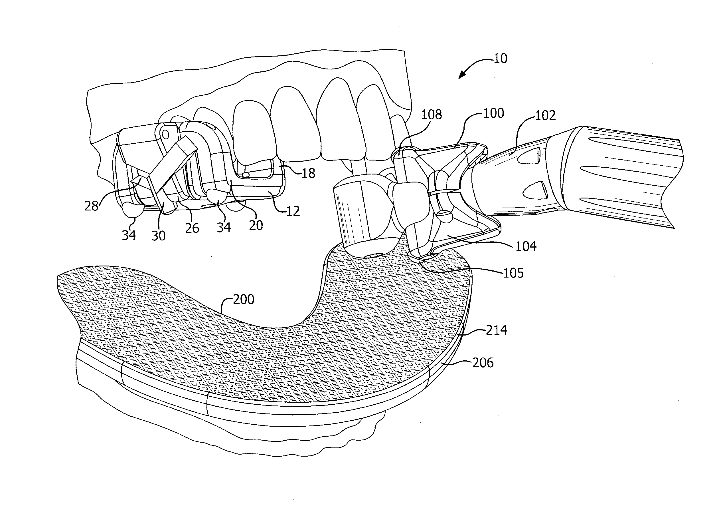
[0067]Referring now to FIGS. 7 and 8, a reference dental appliance or fixture 200 according to one embodiment is shown for use with a lower set of teeth in a patient. FIGS. 9 and 10 illustrate the reference fixture 200 for use with a upper set of teeth. in one embodiment, the reference fixture 200 includes a base plate 202 with inner and outer raised edges 204, 206 formed integral with and extending outward from the base plate 202. As with the oral fixture 12, the reference fixture 200 may include one or more surface irregularities (not shown), such as protrusions or indentations, formed on the base plate 202. The raised edges 204, 206 preferably also include surface irregularities 208, such as indentations as shown. The reference fixture 200 is preferably made from the same or similar material as the camera support 14 since it is also designed to be attached to the patient's teeth using a moldable material. Specifically, referring to FIG. 11, a moldable material 210, preferably sim...

embodiment 300

[0092]While the above discussion involved the use of a video tracking system that includes cameras mounted to the oral fixture and the tool fixture in combination with a reference plate, other arrangements are also contemplated. For example, in one alternate embodiment 300 shown in FIG. 13, the oral fixture 12 does not include a camera and camera mount but is otherwise constructed similar to the prior embodiment and mounted to a patient's teeth or secured to the bone as discussed above. The oral fixture 12 includes a fixture reference pattern 302, similar to reference pattern 212, that is applied to or formed on a surface of the oral fixture 12. Also, in this embodiment, the tool 102 does not include a tool fixture 100 but, instead, includes a tool reference pattern 304, again similar to reference pattern 212. There are two cameras 306 mounted on the reference plate 200, one positioned so as to visually detect the location of the fixture reference pattern 302 and the other to visual...

embodiment 310

[0093]Referring to FIG. 14, another embodiment 310 of the invention is shown. In this embodiment, the oral fixture 12 includes a fixture reference pattern 302 as discussed above. The tool 102 includes a tool fixture 100 similar to the tool fixture described above but with only one camera 312 oriented toward the reference pattern 212 on the reference plate 200. The reference plate 200 also includes a camera 306 mounted so as to detect the fixture reference pattern 302 on the oral fixture 12. From the video data from the two cameras and the detection of the two patterns, the system is capable of correlating the CT scan to the actual orientation of the mouth and depict the location of the tool on the scan.


PUM


Abstract

An image guidance system for tracking a surgical instrument within the oral cavity. The image guidance system includes a plurality of cameras adapted to be located within the oral cavity to provide intraoral images of optically visible patterns within oral cavity. A processing system receives and processes the intraoral images to recognize patterns and triangulate the locations and orientations of each camera. The processing system uses a reference dataset which defines a reference coordinate system based on alignment to a portion of the oral anatomy. The processing system determines the location and orientation of the tracked instrument based on the reference dataset. In an embodiment, the system includes an oral fixture that is removably attachable to teeth in a patient and is configured to hold one of the cameras.

Description

RELATED APPLICATION[0001]This application is related to and claims priority from U.S. Provisional Patent Application 61 / 782,255, filed Mar. 14, 2013, the disclosure of which is incorporated herein by reference in its entirety.FIELD OF THE INVENTION[0002]The present invention relates to a system for facilitating image guided surgery and, more particularly to an improved image guided system for oral surgery.BACKGROUND[0003]Image guided surgery has had extensive developments over the years and is now a very important tool in surgical procedures. Most of the developments have centered around imaging locations in the body where there is very little access, such as internal organs.[0004]Oral surgery, which is defined herein as any surgery occurring within the oral cavity, can be just as difficult to conduct visually. The oral cavity is relatively small and difficult for a patient to maintain open for prolonged periods of time. Even if a surgical site is visible, once the drill penetrates,...

Claims


Application Information

Patent Timeline
Patent Type & Authority Applications(United States)
IPC IPC(8): A61B5/00A61B6/14A61B6/03
CPCA61B5/0088A61B5/0077A61B2019/5466A61B6/145A61B2019/5483A61B6/032A61B6/12A61B6/14A61B6/4417A61B6/5247A61B1/24A61C9/004A61C19/04A61C1/082A61B2090/3983A61B90/16A61B1/00148A61B34/20
Inventor MERRITT, SCOTT A.EMERY, ROBERT W.MARANDOLA, EDWARD J.SCHARFF, CHRISTOPHER W.
Owner X NAV TECH
Why Eureka
Try Eureka