Automatic Splice Having An Arm Indicator

a technology of arm and arm connector, which is applied in the direction of incorrect coupling prevention, coupling device connection, electrical apparatus, etc., can solve the problems of unsplicing of conductors, untimely splicing of electrical conductors, and lack of an indication of electrical conductors, so as to reduce the force required to insert first, and prevent unintended movement of indicators

Active Publication Date: 2014-09-18
HUBBELL INC
View PDF4 Cites 7 Cited by
  • Summary
  • Abstract
  • Description
  • Claims
  • Application Information

AI Technical Summary

Benefits of technology

[0008]Still another object of the present invention is to provide a cable connector that reduces the force required to insert first and second cables.
[0009]The foregoing objectives are basically attained by a cable connector including a body member having a cable opening to receive a cable and an indicator opening. An indicator is movable between first and second positions. A stop member releasably engages and substantially prevents unintended movement of the indicator from the first position to the second position. The indicator moves past the stop member and through the indicator opening in the body member when moving from the first position to the second position and is exposed externally of the body member to indicate full insertion of the cable.
[0010]The foregoing objectives are also basically attained by a cable connector including a body member having a cable opening to receive a cable and an indicator opening. A centerstop is disposed in the body member and has a pivot member. An indicator is movably connected to the pivot member and pivotable between first and second positions. A stop member connected to the centerstop releasably engages and substantially prevents unintended movement of the indicator from the first position to the second position. The ind

Problems solved by technology

A problem associated with existing automatic splices is the lack of an indication that the electrical conductors have been fully inserted in the automatic splices.
Without such indication, the conductors can be partially inserted, such that the conductors are not properly spliced together.
Failure to fully insert a conductor in the splice can result in the conductor slipping out of the splice, which could take time to occur, thereby creating a h

Method used


Image

  • Automatic Splice Having An Arm Indicator
  • Automatic Splice Having An Arm Indicator
  • Automatic Splice Having An Arm Indicator

Examples


Embodiment Construction

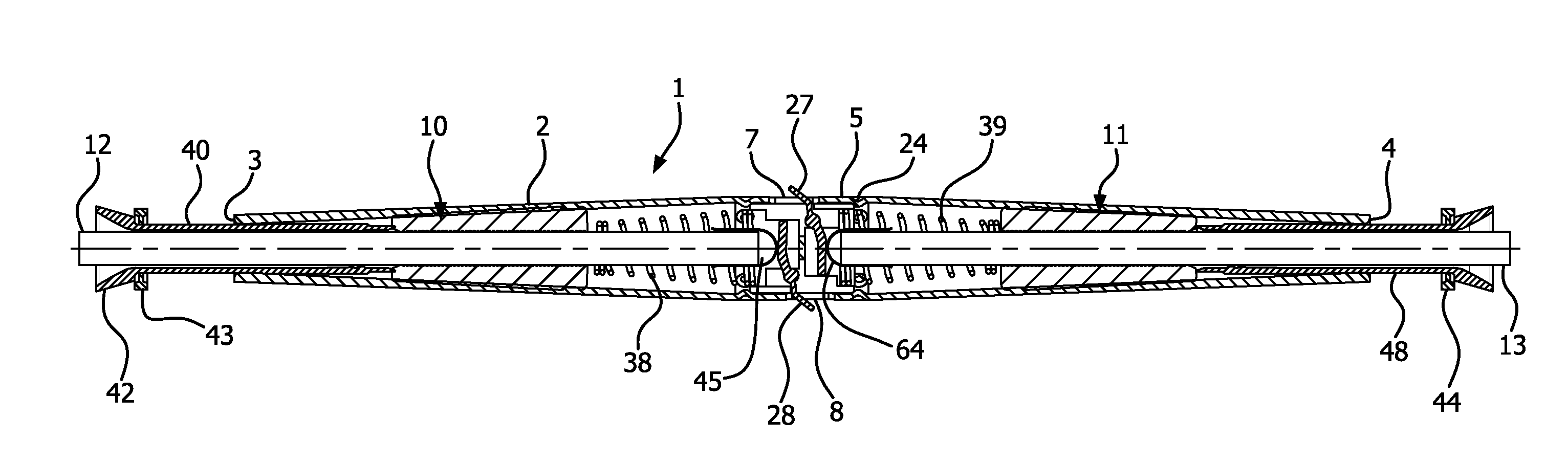
[0038]A cable connector, or automatic splice, 1 in accordance with an exemplary embodiment of the present invention includes a body member 2 having a cable opening to receive a cable 12 and an indicator opening 7. An indicator 27 is received in the indicator opening 7 and is movable between unexposed and exposed positions.

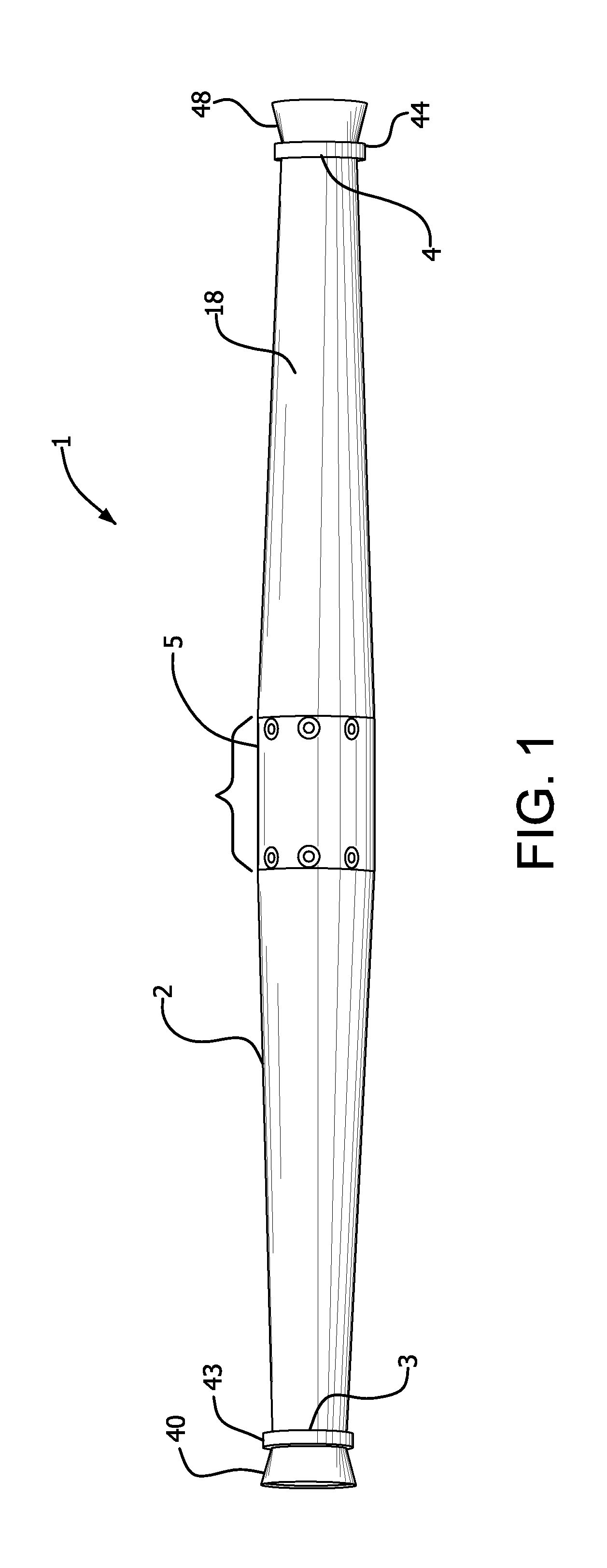
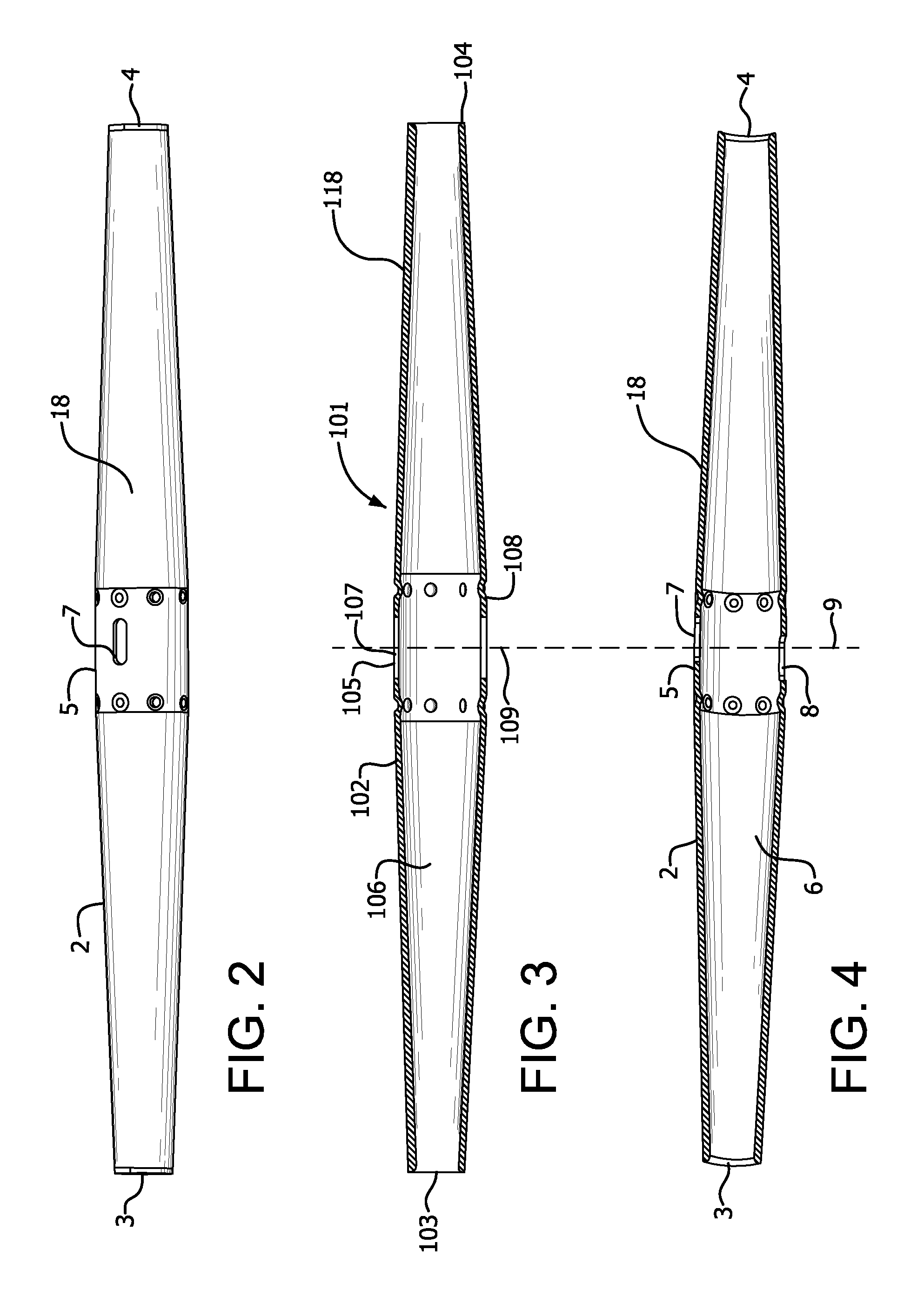
[0039]The swaged tube, or body member, 2 has first and second ends 3 and 4, as shown in FIGS. 1, 2 and 4. The tube 2 has a center portion 5 having a substantially constant diameter. The diameter of the tube 2 decreases and tapers internally from the center portion 5 toward each of the first and second ends 3 and 4, as shown in FIG. 4. A cavity 6 is defined by the tube 2 between the first and second ends 3 and 4. A plurality of dimples 24 extend inwardly from the center portion 5 of the tube. As shown in FIGS. 1, 2 and 4, first and second sets of dimples extend circumferentially around the tube on opposite sides of first and second indicator openings 7 and 8. The tu...


PUM


Abstract

A cable connector includes a body member having a first opening to receive a cable and a second opening. An indicator is movable between first and second positions. A stop member substantially prevents unintended movement of the indicator from the first position to the second position. The indicator moves past the stop member and through the second opening in the body member when moving from the first position to the second position and is exposed externally of the body member to indicate full insertion of the cable.

Description

CROSS REFERENCE TO RELATED APPLICATION[0001]This application claims the benefit under 35 U.S.C. §119(e) of U.S. Provisional Application Ser. No. 61 / 794,436, filed Mar. 15, 2013, which is hereby incorporated by reference in its entirety.FIELD OF THE INVENTION[0002]The present invention relates generally to a cable connector splice for electrically and mechanically connecting first and second cables. More particularly, the present invention relates to a cable connector indicating full insertion of a cable therein. Still more particularly, the present invention relates to a cable connector in which an indicator is pivoted out of the connector upon full insertion of a cable.BACKGROUND OF THE INVENTION[0003]Splicing connectors for electrical cables and conductors have long been known, and are used by utility linemen to quickly splice lengths of suspended cable together. The splicing connectors, commonly referred to as automatic splices, have become a mainstay in the electrical utility in...

Claims


Application Information

Patent Timeline
IPC IPC(8): H01R13/641
CPCH01R13/641H01R4/5083H01R4/52H02G1/14
Inventor DIOP, SEYDOUZELAZNY, PAUL
Owner HUBBELL INC
Why Eureka
Try Eureka