

Infusion fluid warmer
- Summary
- Abstract
- Description
- Claims
- Application Information
AI Technical Summary
Benefits of technology
Problems solved by technology
Method used
Image

Examples
first embodiment
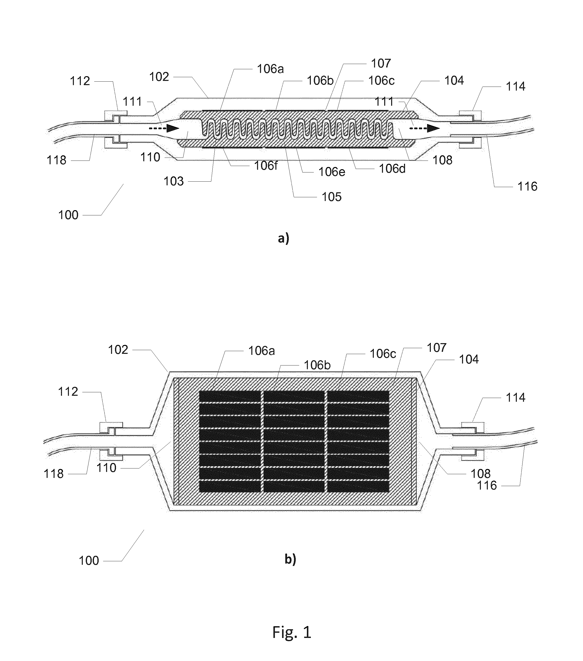
[0039]FIG. 1a) shows a vertical cross-sectional view of an infusion fluid warmer 100 in accordance with the invention. The infusion fluid warmer 100 comprises a housing shell 104 formed in a thermally conducting and electrically insulating material, preferably comprising a ceramic material such as Aluminium Oxide (Al2O3). The dimensions of the housing shell 104 may vary in accordance with specific requirements for the infusion fluid warmer 100, in particular its fluid warming capacity.
[0040]The housing shell 104 is encapsulated or enclosed within an outer casing 102 which may be formed in a suitable polymeric material for example a thermoplastic material or elastomeric compound by injection moulding. The outer casing 102 may be shaped and sized to protect the housing shell 104 from mechanical shocks and impacts. A pair of cap nuts or caps 112, 114 covers respective entrance openings of the outer casing 102 and is preferably used to seal or isolate the interior volume of the outer ca...
embodiment 100
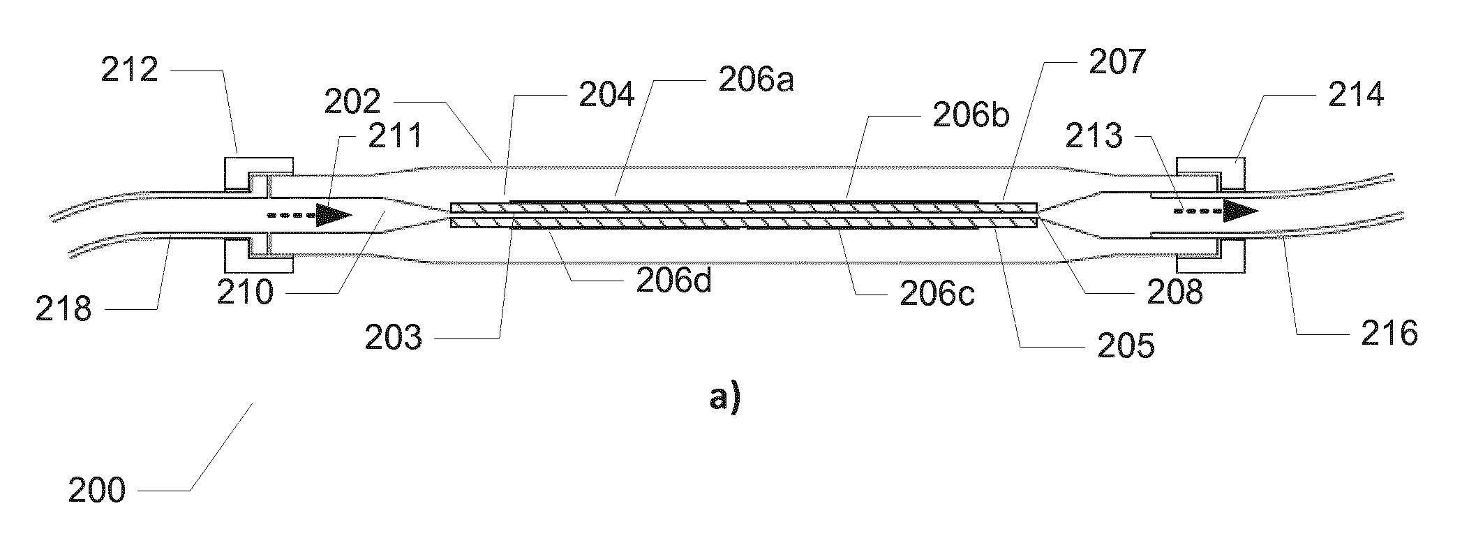
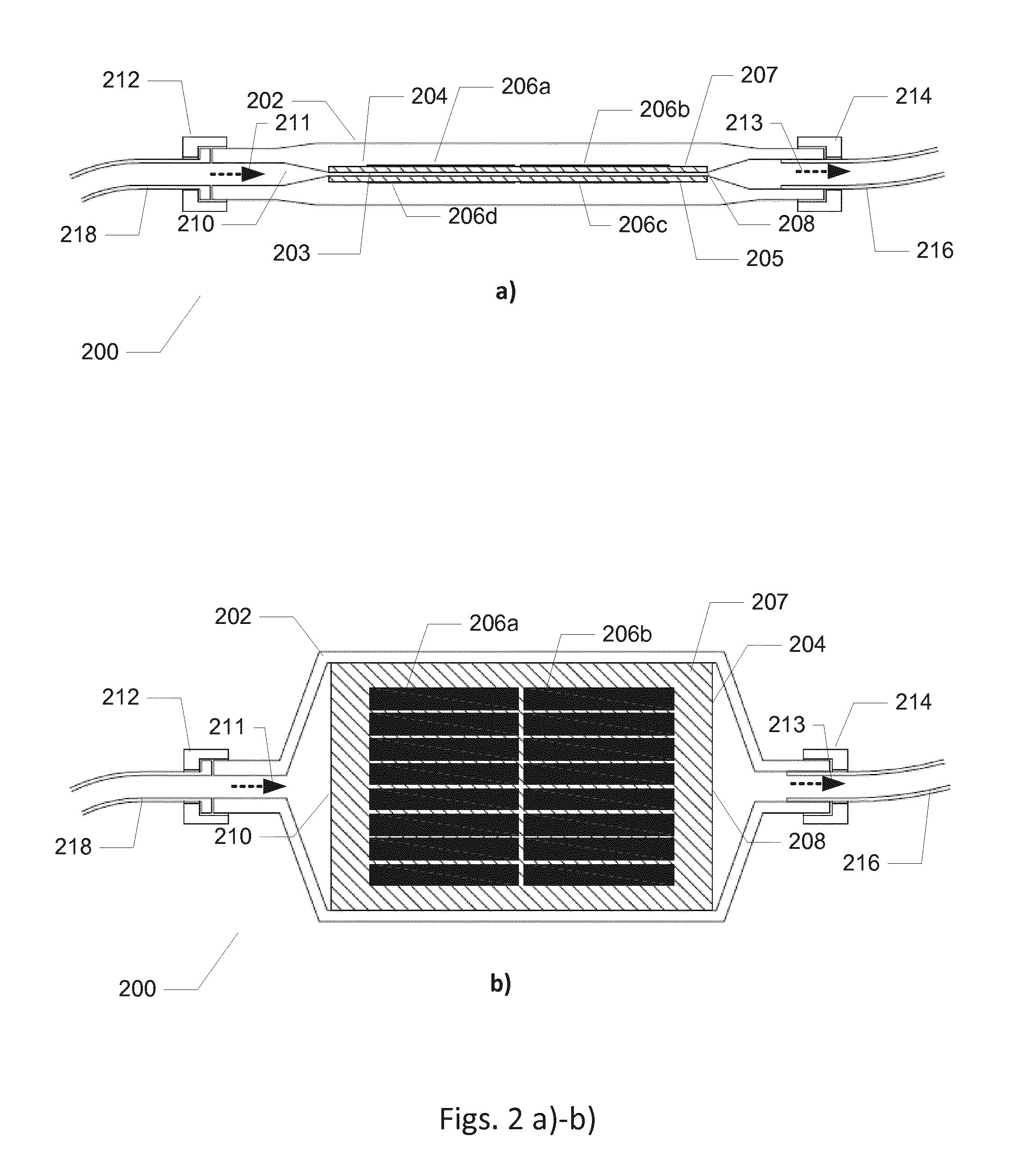
[0048]The infusion fluid warmer 200 may comprise a temperature sensor (not shown) for determining a temperature of the infusion fluid in the fluid channel 203 for example at the outlet port 208. The temperature sensor may be utilized to ascertain the infusion fluid temperature lies within a certain allowable range for example between 36 and 37 degree Celsius. A controller circuit (not shown) is operatively coupled to the temperature sensor and to the array of thick film resistors 206a-206d to control instantaneous power dissipation in the array in the same manner as described above in connection with the first infusion fluid warmer embodiment 100.
[0049]The skilled person will appreciate the firm bonding between the array of thick film resistors 206a-206d and the housing shell 204 provides a compact unitary assembly of heating element and heat exchanger with a low parts count in the present infusion fluid warmer 200.
second embodiment
[0050]FIG. 2b) shows a top view of the infusion fluid warmer 200 in accordance with the invention. The lid or upper wall of the thermoplastic casing 202 has been removed such that the outer surface of the upper wall 207 of the housing shell 204 is exposed. The thick film resistors 206a, 206b are disposed on the outer surface of the upper wall 207 covering a large portion of the available surface area. Each of the thick film resistors 206a, 206b comprises a plurality of individual resistor segments arranged in width wise direction. These resistor segments may be coupled in series or parallel to provide a desired resistance value of the thick film resistor in question.
[0051]FIG. 2c) illustrates a vertical cross-sectional view of an infusion fluid warmer 250 in accordance with a third embodiment of the invention. Similar features and elements of the present embodiment and the above-described second embodiment of the infusion fluid warmer have been provided with corresponding reference ...
PUM
 Abstract
Description
Claims
Application Information