Eureka AIR delivers breakthrough ideas for toughest innovation challenges, trusted by R&D personnel around the world.

Spinal implant and assembly

Active Publication Date: 2014-09-18
X SPINE SYST
View PDF5 Cites 59 Cited by
  • Summary
  • Abstract
  • Description
  • Claims
  • Application Information

AI Technical Summary

Benefits of technology

The patent is about an implant that has arms to keep a screw in place and prevent it from coming out of the implant or bone. The goal is to ensure the screw stays secure and can do its job.

Problems solved by technology

Among some of the problems associated with the prior art devices is that after the device is inserted into a patient during a surgical procedure, there was a possibility of retropulsion of the inter-body device and graft material into the spinal cord or other neurological element.
Another problem with the prior art devices is that grafting material, which was inserted into the devices during the surgical procedure, could not easily be inserted from an anterior direction.
Another problem with some prior art systems is that the screws or fasteners which secured implant to bone sometimes had a tendency to unscrew themselves because the implant itself may move or withdraw.
While solutions for retaining screws in the implant plates have included, for example, the use of a resilient arm and approaches used in U.S. Pat. No. 7,641,701, these approaches do not work as effectively with implants that use angled screws.
Such approaches are also not practical for use with implants that do not have available space for using an arm.

Method used


Image

  • Spinal implant and assembly
  • Spinal implant and assembly
  • Spinal implant and assembly

Examples


Embodiment Construction

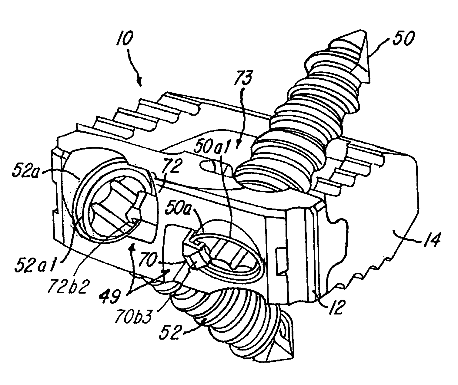
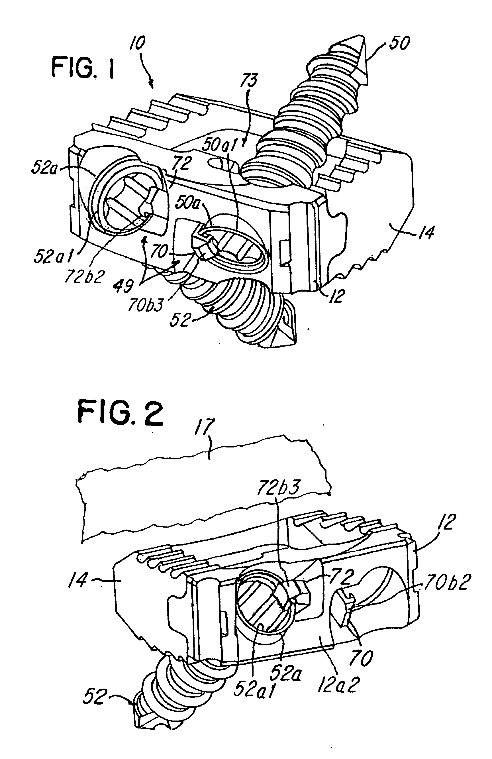
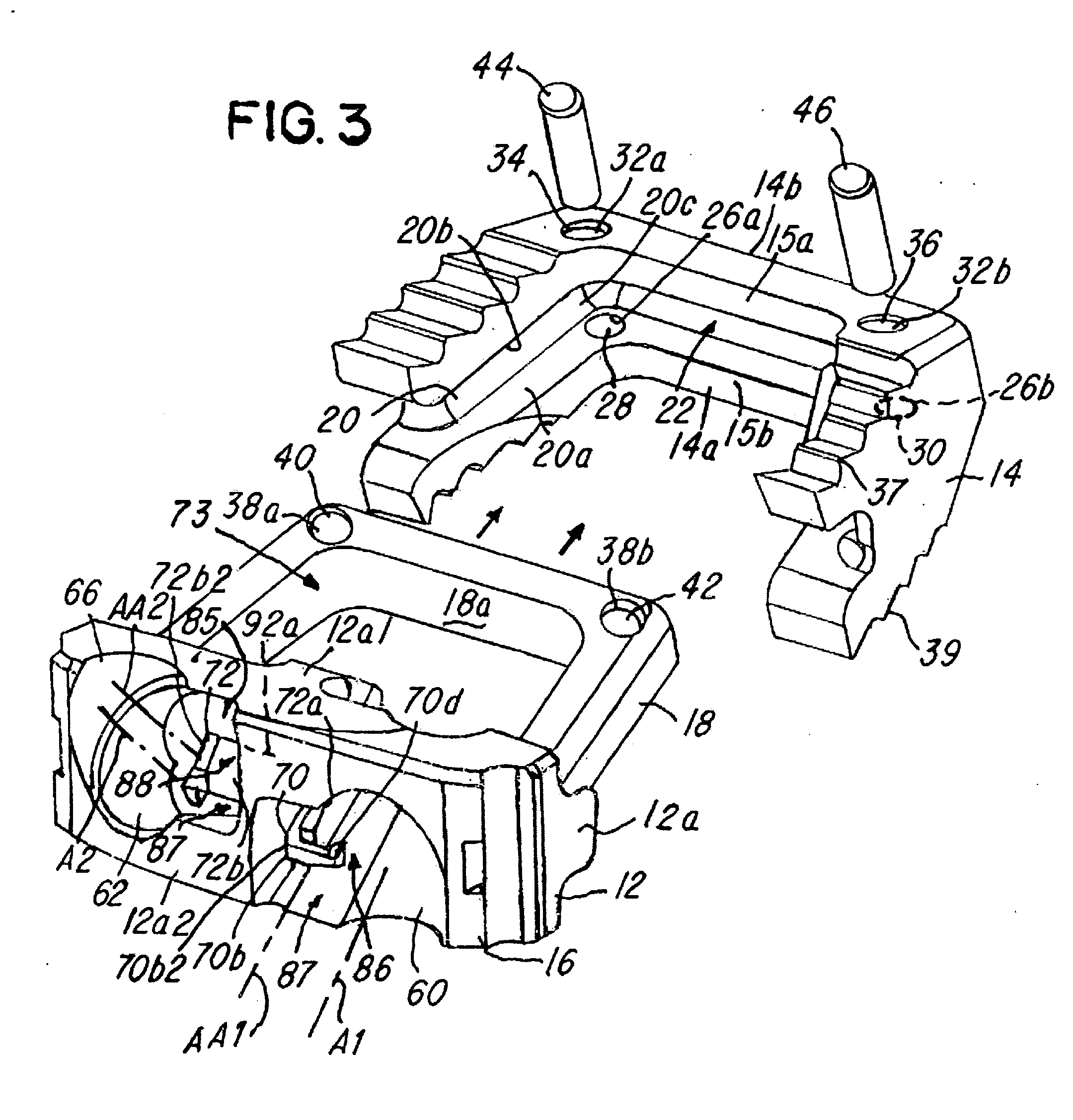
[0034]Referring now to FIGS. 1-12, an implant and an implant assembly 10 are shown. The implant assembly 10 comprises a first implant member 12 and a second implant member 14. The implant assembly 10 is adapted to be received in an implant assembly receiving area 15 (FIG. 4) between bones, such as between a first vertebra or bone 17 and a second vertebra or bone 19. The second implant member 14 has an open-end configuration as illustrated in FIG. 3. Further details of the second implant member 14 will be described later herein. Although not shown, it should be understood that the first implant member 12 could have an open-end configuration with U-shaped channel (not shown) and the second implant member 14 could have a mating U-shaped projection (not shown) for receipt in the U-shaped channel.

[0035]The first implant member 12 comprises a first wall 16 having a generally U-shaped projection 18. As best illustrated in FIG. 3, note that the second implant member 14 comprises a generally...


PUM


Abstract

An implant assembly is shown and described. The implant has at least one or a plurality of elastic, resilient or flexible arms that each have a detent adapted to retain at least one screw in a locked position in the implant. At least one of the arms has a portion that extends into a screw aperture such that an arm axis is generally parallel to the axis of the screw after the screw is received in the implant. In another embodiment, means or a system for locking the multi-component implant members together is shown.

Description

BACKGROUND OF THE INVENTION[0001]1. Field of the Invention[0002]This invention relates to spinal implants, and more specifically, the invention relates to an implant having at least one resilient, elastic or flexible arm adapted to have an arm axis that becomes generally parallel to an axis of a screw that is received in the implant.[0003]2. Description of the Related Art[0004]Many types of prosthetic devices have been proposed in the past. For example, U.S. Pat. No. 5,192,327 to Brantagan concerns a surgical prosthetic modular implant used singularly or stacked together to support and fuse together adjacent vertebrae or to totally or partially replace one or more vertebrae in a vertebral column. Other surgical implant devices and methods are shown in U.S. Pat. Nos. 5,192,327; 5,261,911; 5,713,899; 5,776,196; 6,136,002; 6,159,245; 6,224,602; 6,258,089; 6,261,586; 6,264,655; 6,306,136; 6,328,738; 6,592,586; 7,182,782 and 7,641,701. Some or all of these devices have improved the succe...

Claims


Application Information

Patent Timeline
IPC IPC(8): A61F2/44
CPCA61F2/4455A61F2/447A61F2002/30004A61F2002/30014A61F2002/30131A61F2002/30383A61F2002/30492A61F2002/30604A61F2002/30787A61F2002/30904A61F2002/30593
Inventor KIRSCHMAN, DAVID LOUIS
Owner X SPINE SYST
Why Eureka
Eureka Blog
Learn More