Eureka AIR delivers breakthrough ideas for toughest innovation challenges, trusted by R&D personnel around the world.

Boat lift operated by boat's propulsive force

a technology of propulsive force and boat, which is applied in the field of boat lift, can solve the problems of large time and money spent by owners, pits and other surface imperfections in common hull materials like fiberglass and wood, and the maintenance of a boat hull left in water can require significant time and money

Active Publication Date: 2011-10-06
SMITH JOSHUA ADAM
View PDF5 Cites 12 Cited by
  • Summary
  • Abstract
  • Description
  • Claims
  • Application Information

AI Technical Summary

Benefits of technology

[0014]It is an object of the present invention to provide a boat lift that overcomes the aforementioned drawbacks, by using the boat's own propulsive thrust to provide the power for operating a boat lift mechanism, which eliminates the need for electrical or hydraulic power at the dock, while providing rapid launch and retrieval of the boat, and providing compatibility with the constrained space associated with covered docks.
[0017]Additional aspects of the invention include such a boat lift wherein the linkage is a mechanical linkage, which optionally can comprise at least one cable attached to the first and second trolleys and having an intermediate portion between the trolleys passing over at least one pulley mounted to the lift frame. A particularly advantageous embodiment has two such pulleys to cause the lower trolley to halve the distance travelled by the first trolley relative to the distance travelled by the second trolley.
[0018]In yet another aspect of the invention, the boat lift as installed in the boat dock has the lift frame resting in a boat receiving position with the boat cradle positioned relative to the water level for accepting the hull of the boat, and the boat lift further comprises a releasable second trolley lock for securing the second trolley in a terminal position into which it has been moved by the boat after completion of a docking operation that moves the boat lift into a final docking position, in which the second trolley lock prevents movement of the second trolley in a direction opposite to the direction of boat travel during the docking operation, and a releasable boat retainer moved into a boat retaining position by the first trolley for retaining the boat in place on the boat cradle when the second trolley is locked in the terminal position thereof. In an advantageous variation of this aspect of the invention, the dock cooperates with the lift frame in the final docking position to hold the lift frame relative to the water line in a position at which a force is exerted on the first trolley urging it in a direction opposite to the direction it traveled during the docking operation.
[0020]The method can advantageously be carried out with the flotation device shaped to exert a force on the boat lift in the presence of water flow induced by the propulsive power of the boat tending to maintain the boat lift in the rotated docking position. The boat lift can optionally include a mechanism such as a gas strut for assisting in maintaining the boat lift in the rotated docking position during application of the boat's propulsive power.

Problems solved by technology

Recreational boat owners can spend large amounts of time and money on maintenance and repair of their vessels.
Leaving a boat or other craft in water for long periods can cause build up on the hull of algae (in fresh water) and barnacles (in salt water), and can cause pits and other surface imperfections in common hull materials like fiberglass and wood.
Maintenance of a boat hull left in water can require significant expenditures of time and money.
Rather than using labor-intensive and often costly approaches such as specially formulated paints or other surface treatments, many boat owners elect to keep their boats out of the water when not using them.
This type device is most useful with small “personal water craft,” because it is more difficult to launch larger boats from this type of docking device.
Boat lifts that operate manually are burdensome and slow, and all boat owners may not be capable of using them.
In addition, they typically operate slowly, and can take undue time for both docking and launching the boat.
Increasing the operational speed of electrically or hydraulically powered boat lifts can require the use of inordinately large equipment and amounts of electrical power.
Conventionally, a boat lift that relies on the boat to power itself up and onto a buoyant structure would likely have limited utility for larger boats, which would require flotation devices with a relatively large surface area to achieve the necessary buoyancy.
This could make such devices incompatible with covered docks that have limited available space.
Likewise, launching large, heavy boats docked with such devices is more difficult, as well.
However, none is completely satisfactory as a boat lift for many existing types and sizes of boats and other water craft, nor are they all adaptable for use with different configurations and sizes of docks.

Method used


Image

  • Boat lift operated by boat's propulsive force
  • Boat lift operated by boat's propulsive force
  • Boat lift operated by boat's propulsive force

Examples


Embodiment Construction

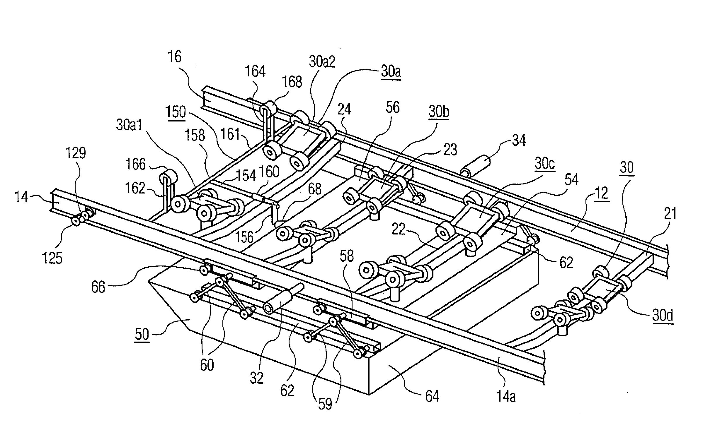
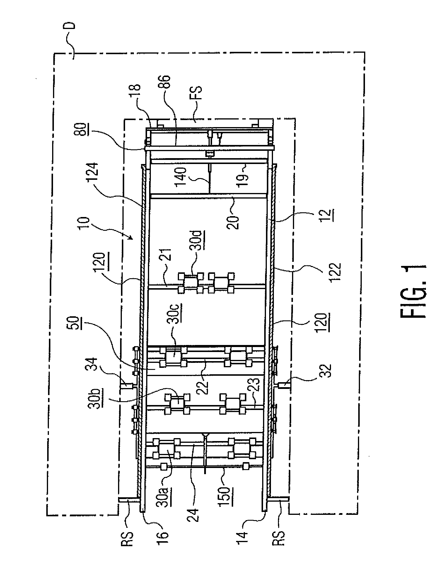
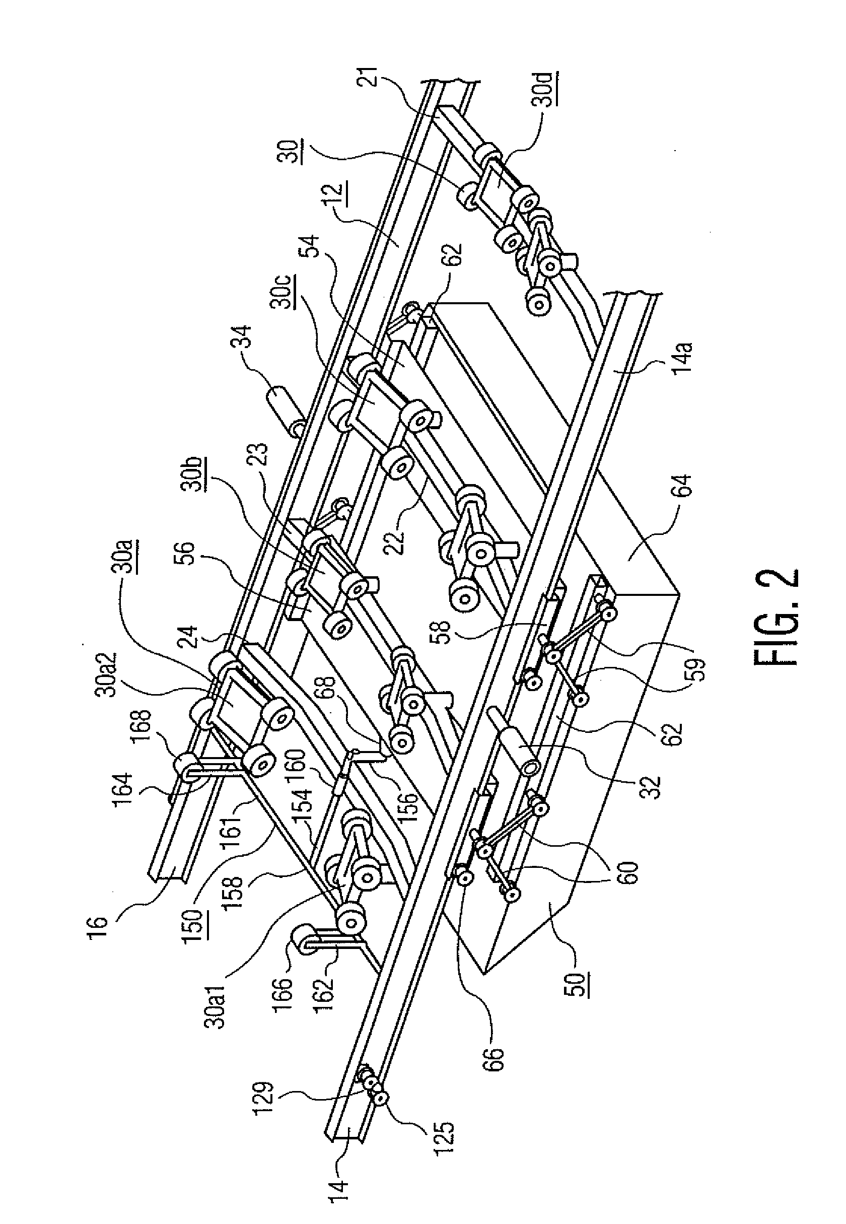
[0032]Referring to FIGS. 1 and 2, a boat lift 10 in accordance with a first embodiment of the present invention includes a lift frame 12 that has two generally parallel side rails 14 and 16 connected by cross braces 18, 19, 20, 21, 22, 23 and 24. The number and placement of the cross members is optional, their purpose being to provide sufficient rigidity to the frame 12 to accomplish the purposes of the boat lift in accordance with this description. The frame 12, with side rails 14 and 16 and cross braces 18 to 24, will typically be a unitary, welded structure, but those skilled in the art will appreciate that the frame can be fabricated in other ways as well. The frame 12 also includes a boat cradle 30 that comprises a plurality of roller assemblies 30a, 30b, 30c and 30d. Taking as representative the roller assembly 30a, it includes two roller dollies 30a1 and 30a2, each of which is supported on the frame cross brace 24. In the depicted embodiment, each roller dolly includes four h...


PUM


Abstract

A boat lift uses the boat's own propulsive force to lift the boat out of the water. The boat lift comprises a lift frame mounted to a boat dock for rotation, and in a boat receiving position is rotated so that the boat can propel itself onto a boat cradle on the lift frame. A lower trolley slidably mounted on the frame includes a buoyant body in the water for exerting an upward force on the frame. An upper trolley slidably mounted on the frame is engaged by the boat as it propels itself forward onto the boat cradle. The upper trolley is linked to the lower trolley to cause the lower trolley to slide rearwardly under the boat, thus moving the buoyant body rearwardly and rotating the lift frame into a final docking position in which the boat is lifted out of the water. The upper trolley is locked into position, thus locking the lower trolley in position through the linkage between them, and a boat retainer actuated by the lower trolley engages the rear of the boat to hold it on the boat cradle. The boat is launched by releasing the upper trolley lock, which permits the upper trolley to slide rearwardly, with concomitant forward sliding movement of the lower trolley that releases the boat retainer. The forward movement of the lower trolley permits the frame to rotate and launch the boat from the rear of the frame. When a boat is not mounted on the lift, it rests in the boat receiving position.

Description

BACKGROUND OF THE INVENTION[0001]1. Field of the Invention[0002]The present invention relates to a boat lift, and more particularly, to a boat lift that uses the boat's propulsive force to lift the boat from the water.[0003]2. Description of Related Art[0004]Recreational boat owners can spend large amounts of time and money on maintenance and repair of their vessels. Leaving a boat or other craft in water for long periods can cause build up on the hull of algae (in fresh water) and barnacles (in salt water), and can cause pits and other surface imperfections in common hull materials like fiberglass and wood. Maintenance of a boat hull left in water can require significant expenditures of time and money. Rather than using labor-intensive and often costly approaches such as specially formulated paints or other surface treatments, many boat owners elect to keep their boats out of the water when not using them.[0005]There are many types of boat lifts suitable for removing boats from the...

Claims


Application Information

Patent Timeline
Patent Type & Authority Applications(United States)
IPC IPC(8): B63C3/12
CPCB63C3/02B63C1/02
Inventor SMITH, J. WALTER
Owner SMITH JOSHUA ADAM
Why Eureka
Eureka Blog
Learn More